
Aspiring engineers who are preparing for the Graduate Aptitude Test in Engineering (GATE) understand the significance of thorough preparation and comprehensive study resources.
Through a meticulous examination of previous years’ question papers, we aim to provide you with valuable insights, key trends, and effective strategies to excel in Analog Electronics for your GATE exam.
GATE EE Syllabus for the Subject Analog Electronics
Simple diode circuits: clipping, clamping, rectifiers;
Amplifiers: biasing, equivalent circuit and frequency response; oscillators and feedback amplifiers;
Operational amplifiers: characteristics and applications; single stage active filters, Active Filters: Sallen Key, Butterworth, VCOs and timers;
Combinatorial and sequential logic circuits, multiplexers, demultiplexers, Schmitt triggers, sample and hold circuits, A/D and D/A converters.
Analysis of Previous GATE Papers for Analog Electronics
| Year | Percentage of Marks |
|---|---|
| 2023 | 6% |
| 2022 | 7 % |
| 2021 | 3 % |
| 2020 | 8 % |
| 2019 | 6 % |
| 2018 | 7 % |
| 2017 | 5% |
| 2016 | 10% |
| 2015 | 14.50 % |
| 2014 | 12.33 % |
| 2013 | 5 % |
Recent GATE Paper Questions of Analog Electronics
The following questions have been asked from Analog Electronics, in GATE-EE 2023 Paper.
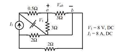
Q. For the circuit shown in the figure, V1 = 8 V, DC and I1 = 8 A, DC. The voltage Vab in Volts is ____ (Round off to 1 decimal place)
Q. 2. Consider the OP AMP based circuit shown in the figure. Ignore the conduction drops of diodes D1 and D2. All the components are ideal and the breakdown voltage of the Zener is 5 V. Which of the following statements is true? [02 M]
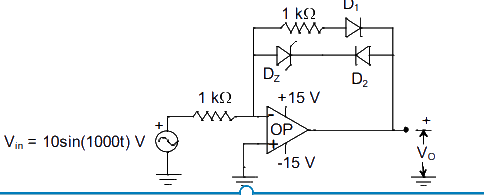
A) The maximum and minimum values of the output voltage VO are +15 V and -10 V, respectively.
B) The maximum and minimum values of the output voltage VO are +5 V and -15 V, respectively
C) The maximum and minimum values of the output voltage VO are +10 V and -5 V, respectively.
D) The maximum and minimum values of the output voltage VO are +5 V and -10 V, respectively.
Q. All the elements in the circuit shown in the following figure are ideal. Which of the following statements is/are true?
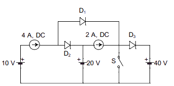
A) When switch S is ON, both D1 and D2 conducts and D3 is reverse biased
B) When switch S is ON, D1 conducts and both D2 and D3 are reverse biased
C) When switch S is OFF, D1 is reverse biased and both D2 and D3 conduct
D) When switch S is OFF, D1 conducts, D2 is reverse biased and D3 conducts
GATE Paper Solutions for Analog Electronics
Last 25+ years GATE Papers with Authentic Solutions