GATE EE 2021 Solved Paper
Q.1 — Q.5 Multiple Choice Question (MCQ), carry ONE mark each (for each wrong answer: — 1/3).
Q.1 The people _______ were at the demonstration were from all sections of society.
a) whose
b) which
c) who
d) whom
Ans: c) who
Solution:- The subject of the verb is ‘who’. Therefore, option (c) is the correct answer.
Q.2 A transparent square sheet shown below is folded along the dotted line. The folded sheet will look like ____.
Ans: c)
Solution: As the given diagram on page appears like a triangle so when it is folded along the dotted line it will turn into two traingle so option (c) is correct.
Q.3 For a regular polygon having 10 sides, the interior angle between the sides of the polygon, in degrees, is:
a) 396
b) 324
c) 216
d) 144
Ans: d) 144
Solution:- We know that the interior angle of polygon is given by =frac{(2n-4)90^{o}}{n}
n is the number of sides.
n=10,
=frac{(2x 10 -4)90^{o}}{10} = 144o
So, option (d) is correct.
Q.4 Which one of the following numbers is exactly divisible by (1113+1)?
a) 1126+1
b) 1133+1
c) 1139-1
d) 1152-1
Ans: d) 1152-1
Solution:- Comparing the given expression i.e. (1113+1) with the formula an-bn
1113=a and 113 = b
an-bn is divisible by (a+b) only when n is even
Let us check by putting one by one option.
Take option (3) into consideration
frac{11^{52}-1^{52}}{11^{13}-1^{13}}=frac{(11^{3})^{4}-(1^{3})^{4}}{11^{13}+1^{13}} =frac{a^{4}-b^{4}}{a+b}So, option (d) is correct.
Q.5 Oasis is to sand as island is to _______
Which one of the following options maintains a similar logical relation in the above sentence?
a) Stone
b) Land
c) Water
d) Mountain
Ans: c) Water
Solution: Oasis is the waterpool within the sand same as island is the piece of land within water. It is an example of analogy.
Q. 6 — Q. 10 Multiple Choice Question (MCQ), carry TWO marks each (for each wrong answer: — 2/3).
Q.6 The importance of sleep is often overlooked by students when they are preparing for exams. Research has consistently shown that sleep deprivation greatly reduces the ability to recall the material learnt. Hence, cutting down on sleep to study longer hours can be counterproductive.
Which one of the following statements is the CORRECT inference from the above passage?
a) Sleeping well alone is enough to prepare for rim exam. Studying has lesser benefit.
b) Students are efficient end ore not wrong in thinking that sleep is a waste of time.
c) If a student is extremely well prepared for rim exam, he needs little or no sleep.
d) To do well in an exam, adequate sleep must be part of the preparation.
Ans: d) To do well in an exam, adequate sleep must be part of the preparation.
Solution: It is general fact that if we will not sleep properly it will affect our mental health. Deprivation of sleep during exams have negative effect on exams. So, adequate sleep is very very important. So, option (d) is correct.
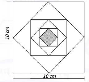
Q.7 In the figure shown below, each inside square is formed by joining the midpoints of the sides of the next larger square. The area of the smallest square (shaded) as shown, in cm2 is:
a) 12.50
b) 6.25
c) 3.125
d)1.5625
Ans: c) 3.125
Solution:- The length of the side of the larger square L1 = 10 cm
We know that the whenever, a square is formed by joining midpoints of the next larger square, area of inner square is exactly of the area of the larger square.
The first small square cuts midway of larger square , so L_{2}=frac{10}{sqrt{2}} cm
The second small square also cuts midway of first small square L_{3}=frac{10}{sqrt{2}^{2}}
We can see taht five sqaures are made, so length of the smallest sqaure is L_{6}=frac{10}{sqrt{2}^{5}}
Therefore, Area of the smallest square = L_{6}^{2}=frac{10}{sqrt{2}^{5}}^2 = 3.125 cm2
So, the area of the smallest square (shaded) = 3.125 cm2
So, option (c)is the correct answer.
Q.8 Let X be a continuous random variable denoting the temperature measured. The range of temperature is [0, 100] degree Celsius and let the probability density function of X be f(x) = 0.01 for 0leq Xleq100. The mean of X is _____
a) 2.5
b) 5.0
c) 25.0
d) 50.0
Ans: d) 50.0
Solution:- The given function is f(x) = 0.01 0leq Xleq100
The mean or expectation of a continuous random variable is given by,
E(x)=int_{infty }^{-infty }x(f(x))dxf(x) is the probability density function (PDF)
The mean or expectation of a continous random variable is given by,
E(x)=int_{0}^{100}x(0.01)dx=50So, option (d) is the correct answer.
Q.9 The number of students passing or failing in an exam for a particular subject are presented in the bar chart above. Students who pass the exam cannot appear for the exam again. Students who fail the exam in the first attempt must appear for the exam in the following year. Students always pass the exam in their second attempt.
The number of students who took the exam for the first time in the year 2 and the year 3 respectively, are
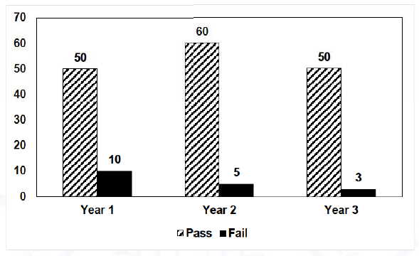
a) 65 and 53
b) 60 and 50
c) 55 and 53
d) 55 and 48
Ans: d) 55 and 48
Solution:-
Given that Students who pass the exam cannot appear for the exam again. Students who fail the exam in the first attempt must appear for the exam in the following year.
So, From the given graph, we can see that there are total 65 students appeared in the year 2 . 10 are from year 1 . So, 55 students appeared for first time in the year -2
In the year 3 53 students appeared for the exam . 5 students(failed in year 2) are from year 2.
So. from this we can say that in year 3, 48 students appeared for the first time.
Therefore, option (c) is the correct answer.
Q.10 Seven cars P, Q, R, S, T, U and V are parked in a roe not necessarily in that order. The cars T and U should be parked next to each other. The cars S and V also should be parked next to each other, whereas P and Q cannot be parked next to each other. Q and S must be parked next to
each other. R is parked to the immediate right of V. T is parked to the left of U. Based on the above statements, the only INCORRECT option given below is:
a) There are two cars parked in between Q and V.
b) Q end R are not parked together.
c) V is the only car parked in between S and R.
d) Car P is parked at the extreme end.
Ans: a) There are two cars parked in between Q and V.
Solution:- From the given condition we can get two possibilities:
- PTUQSVR
- TUQSVRP
Consider following statements depicted from the problem given above.
a) The car T and U should be park next to each other . This means we can park these two cars in two ways, either TU or UT.
b) The car S and V also should be parked next to each other. This means we can park these cars in two ways SV or VS .
c) The car P and Q cannot be parke next to each other This means we cannot park these cars in two ways i.e. Pq and QP.
d) R is parked to the immediate right of V.
e) T is parked to the left of U. The car Q and S must be parked next to each other.
By combining statements b and d we get two possible ways for cars Q, S and V
QSV and VSQ
If we will take one by one possibilities we can see that there can’t be two cause between Q and V .
We can see that the car P can be parked at the xtreme end in three out of the four possible combinations.
So, option a is the correct answer.
Q.1 — Q.12 Multiple Choice Question (MCQ), carry ONE mark each (for each wrong answer: — 1/3).
Q.1 Let p and q be real numbers such that p2 +q2 =1 . The eigenvalues of the matrix begin{bmatrix}p&q\q&-pend{bmatrix} are
a) 1 and 1
b) 1 and -1
c) j and -j
d) pq and -pq
Ans: b) 1 and -1
Solution: The given matrix is A= begin{bmatrix}p&q\q&-pend{bmatrix}
The characteristics equation of the given matrix is
|A-λI| = 0
Solving the determinnat of matrix A we get
λ2– (p-p)λ+(-p2-q2)=0
λ2-1 = 0
λ= ±1
So, option (b) is the correct answer.
Q.2 Let p(Z) = Z3+(1+j)Z2+(2+j)z+3, where z is a complex number. Which one of the following is true?
a) Conjugate {p(Z)}=p(conjugate{Z})for all z
b) The sum of the roots of p(z)=0 is a real number
c) The complex roots of the equation p(z)=0 come in conjugate pairs
d) All the roots cannot be real
Ans: d) All the roots cannot be real
Solution: We know that the general form of cubic equation is ax3+bx2+cx+d = 0
a,b,c are constants and a is not equal to 0 .
Given P(z) = Z3+(1+j)Z2+(2+j)z+3
Sum of roots is p+q+r)= -(1+j)
Product of the roots are = -3
Therefore, the sum of the roots is a complex number.
So, all the roots cannot be real.
So, option (d) is the correct answer.
Q.3 Let f(x) be a real-valued function such that f'(x0)=0 for some x_0;inleft(0,1right), and f”(x)>0 for all x;inleft(0,1right). Then f(x) has
a) no local minimum in (0,1)
b) one local maximum in (0,1)
c) exactly one local minimum in (0,1)
d) two distinct local minimum in (0,1)
Ans: c) exactly one local minimum in (0,1)
Solution: Given that the x_0;inleft(0,1right) where f”(x)>0 is a stationary point.
an f”(x)>0 ∀ x ∈ (0,1)
So, from the given condition f”(xo) = 0
anf f”(0) > 0 , where xo ∈ (0,1)
Therefore, f(x) has exactly local minima in (0,1) which is also called the point of minima.
So, option (d) is the correct answer.
Q.4 For the network shown, the equivalent Thevenin voltage and Thevenin impedance as seen across terminals ‘ab’ is
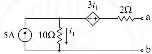
a) 10 V in series with 12Omega
b) 65 V in series with 15Omega
c) 50 V in series with 2Omega
d) 35 V in series with 2Omega
Ans: b) 65 V in series with 15Omega
Solution: The given circuit is
The voltage across terminals a and b is given as VTH
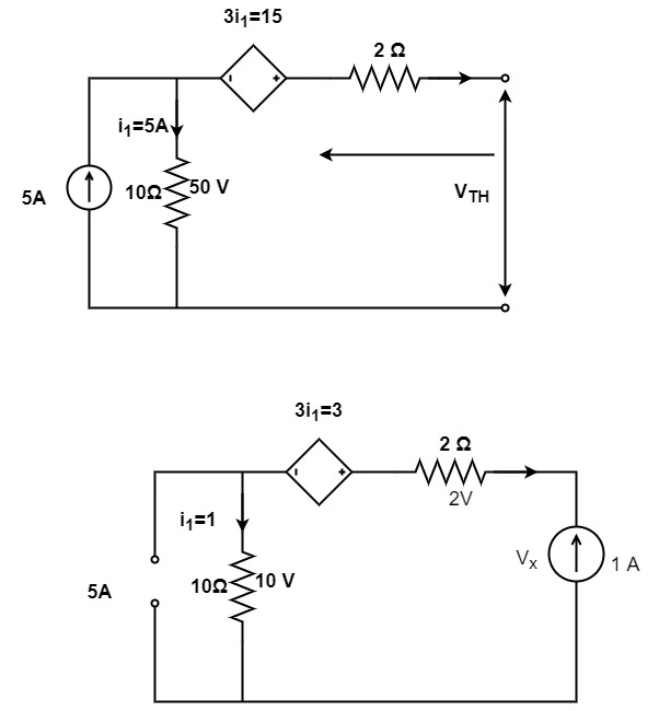
Consider the above circuit for calculating the VTH. As it is open circuit so we will add the voltage sources like 50 V and 15 V
VTH= 15+50 = 65 V
Now deactivating the 5A current source , we get circuit as shown above
Vx = 2+3+10 = 15 V
Calculating thevenin’s resistance,
Thevenin’s resistance is given by, R_TH=frac{V_x}{1} = 15 Ω
The thevenin’s voltage we get is 65 V and Thevenin’s impedance is 15 Ω.
So, option (b) is the correct answer.
Q.5 Which one of the folen circuit lowing vector functions represents a magnetic field overrightarrow B ? ( widehat x,;widehat y;and;widehat z are unit sectors along x-axis, y-axis, and z-axis, respectively)
a) 10xwidehat X+20ywidehat Y-30zwidehat Z
b) 10ywidehat X+20xwidehat Y-10zwidehat Z
c) 10zwidehat X+20ywidehat Y-30xwidehat Z
d) 10xwidehat X-30zwidehat Y+20ywidehat Z
Ans: a) 10xwidehat X+20ywidehat Y-30zwidehat Z
Solution: In general , the magnetic field forms a closed loop i.e. the amount of field leaving a point equals the amount entering i.e. magnetic monopoles do not exist.
As divergence of the field gives the net outflow of field and is calculated as ,
bigtriangledown . overrightarrow{F}So, ∇.B = 0
B= Magnetic flux density
We know that the B is related to H so
B= μH
∇.H = 0
∇.B = 0
frac{partial B_{x}}{partial x}+frac{partial B_{y} }{partial y}+frac{partial B_{z} }{partial z} =0
Let us consider one by one option
Consier option (1) and put value of Bx= 10, By=20, Bz= 30
frac{partial}{partial x}(10x)+frac{partial }{partial y}(20y)+frac{partial }{partial z}(-30z)=bigtriangledown .Bbigtriangledown .B = 10 + 20-30 = 0
So, option (a) is the correct answer as its value is 0.
Q.6 If the input x(t) and output y(t) of a system are related as y(t)=max(0,x(t)), then the system is
a) linear and time-variant
b) linear and time-invariant
c) non-linear and time-variant
d) non-linear and time-invariant
Ans: d) non-linear and time-invariant
Solution: We know that the linear system always follows the laws of superposition i.e. the response of the system is the sum of the responses obtained from each input considered seperately.
y(t)=max(0,x(t)) =left{begin{matrix}0 & x(t)<0\ x(t) & x(t)>0end{matrix}right.I) Checking for linearity we get,
For input x1(t) = -2 , output y1(t) = 0
For input x2(t) =1 , output y2(t) = 1
From this we can say that the system is non-linear as it does not follow law of additivity.
ii) Checking for time invariance
Assume that the output is delayed by to
y(t-t_o) =left{begin{matrix}0 & x(t-t_0)<0\ x(t-t_0)<0 & x(t-t_0)>0end{matrix}right.Let the output of the system is g(t) for delayed input x(t-to)
y_1(t) =left{begin{matrix}0 & g(t)<0\g(t)& g(t) >0end{matrix}right. = left{begin{matrix}0 & x(t-t_0)<0\ x(t-t_0)<0 & x(t-t_0)>0end{matrix}right. = y(t-to)
From this we say that the given system is time -invariant.
So, option (d) is the correct answer.
Q.7 Two discrete-time linear time-invariant systems with impulse response h_1left[nright]=deltaleft[n-1right]+deltaleft[n+1right] and h_2left[nright]=deltaleft[nright]+deltaleft[n-1right] are connected in cascade, where deltaleft[nright] is the Kronecker delta. The impulse response of the cascaded system is
a) deltaleft[n-2right]+deltaleft[n+1right]
b) deltaleft[n-1right]deltaleft[nright]+deltaleft[n+1right]deltaleft[n-1right]
c) deltaleft[n-2right]+deltaleft[n-1right]+deltaleft[nright]+deltaleft[n+1right]
d) deltaleft[nright]deltaleft[n-1right]+deltaleft[n-2right]deltaleft[n+1right]
Ans: c) deltaleft[n-2right]+deltaleft[n-1right]+deltaleft[nright]+deltaleft[n+1right]
Solution: The given discrete system are h_1left[nright]=deltaleft[n-1right]+deltaleft[n+1right] and h_2left[nright]=deltaleft[nright]+deltaleft[n-1right]
The z -transform of a unit impulse function or Kronecker delta δ(n) ⟶ 1
As h1[n] and h2[n] are cascaded connected then h[n] = h1[n] *h2[n]
Here ‘*’ denotes the convolution
h(n) is the resultant impulse response = h1(n) * h2(n)
Applying z -transform , and taking it on both the sides.
H(z) = h1(z).h2(z)
= (z+z-1) (1+z-1)
= z+z-1 +1+z-2
Now let us apply inverse z-transformation
h(n) = δ(n+1)+δ(n-1)+δ(n)+δ(n-2)
we get impulse response as, h(n) = δ(n+1)+δ(n-1)+δ(n)+δ(n-2)
So, option (c) is the correct answer.
Q.8 Consider the table given:
| Constructional feature | Machine type | Mitigation |
| (P) Damper bars | (S) Induction motor | (X) Hunting |
| (Q) Skewed rotor slots | (T) Transformer | (Y) Magnetic locking |
| (R) Compensating winding | (U) Synchronous machine | (Z) Armature reaction |
| (V) DC machine |
The correct combination that relates the constructional feature, machine type and mitigation is
a) P-V-X, Q-U-Z, R-T-Y
b) P-U-X, Q-S-Y, R-V-Z
c) P-T-Y, Q-V-Z, R-S-X
d) P-U-X, Q-V-Y, R-T-Z
Ans: b) P-U-X, Q-S-Y, R-V-Z
Solution: The correct option is (b) because according to the given list of pairs Damper bars is used in synchronous machine for hunting purpose. The Skewed rotor slots is the constructional feature in induction motor and it is used for magnetic locking purpose. The Compensating winding is constructional feature in DCmachine and is used for the mitigation of armature reaction.
Q.9 Consider a power system consisting of N number of buses. Buses in this power system are categorized into slack bus, PV buses and PQ buses for load flow study. The number of PQ buses is NL. The balanced Newton-Raphson method is used to carry out load flow study in polar form. H, S, M, and R are sub-matrices of the Jacobian matrix J as shown below:
begin{bmatrix}triangle P\triangle Qend{bmatrix}=Jbegin{bmatrix}triangledelta\triangle Vend{bmatrix},;where;J=begin{bmatrix}H&S\M&Rend{bmatrix}The dimension of the sub-matrix M is
a) N_Ltimesleft(N-1right)
b) left(N-1right)timesleft(N-1-N_Lright)
c) N_Ltimesleft(N-1+N_Lright)
d) left(N-1right)timesleft(N-1+N_Lright)
Ans: a) N_Ltimesleft(N-1right)
Solution: Given matrix are
begin{bmatrix}triangle P\triangle Qend{bmatrix}=Jbegin{bmatrix}triangledelta\triangle Vend{bmatrix},;where;J=begin{bmatrix}H&S\M&Rend{bmatrix}Let N= Number of buses in the system = N
Number of PQ buses = NL
Number of slack buses = 1
Number of PV buses = N-1 – NL
Newton Raphson method For load flow study in polar form is given by,
begin{bmatrix}triangle P\triangle Qend{bmatrix}=Jbegin{bmatrix}triangledelta\triangle Vend{bmatrix},;where;J=begin{bmatrix}H&S\M&Rend{bmatrix}For size of M
The row indicates the no. of unknown variable of Q=NL
The column indicates the no. of variable which has δ = NL + (N-1-NL) = N-1
Therefore, size of matrix M= NL x (N-1)
So, option (a) is correct.
Q.10 Two generators have cost functions F1and F2. Their incremental-cost characteristics are
frac{dF_1}{dP_1}=40+0.2P_1 frac{dF_2}{dP_2}=32+0.4P_2They need to deliver a combined load of 260 MW. Ignoring the network losses, for economic operation, the generations P1and P2 (in MW) are
a) P1=P2=130
b) P1=160, P2=100
c) P1+140, P2=120
d) P1=120, P2=140
Ans: b) P1=160, P2=100
Solution: Let the incremental cost be denoted by IC1 and IC2
IC1=frac{dF_1}{dP_1}
IC2=frac{dF_2}{dP_2}=32+0.4P_2
For optimum cost, the incremental cost of each generator must be equal ,
IC1=IC2
frac{dF_1}{dP_1} = frac{dF_2}{dP_2}=32+0.4P_2
40 + 0.2 P1 = 32 + 0.4 P2
0.4 P2 – 0.2 P1 = 8
P2 + P1 = 260
Solving simultaneously eq.(i) and (ii)
P1=160 MW , P2 = 100 MW
So, option (b) is correct.
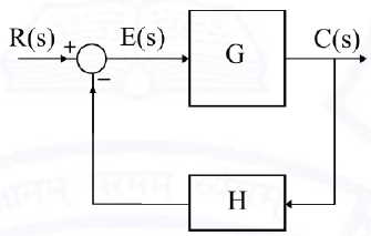
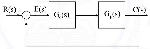
Q.11 For the closed-loop system shown, the transfer function frac{Eleft(sright)}{Rleft(sright)} is
a) frac G{1+GH}
b) frac{GH}{1+GH}
c) frac1{1+GH}
d) frac1{1+G}
Ans: c) frac1{1+GH}
Solution: Given transfer function is frac{Eleft(sright)}{Rleft(sright)}
From the closed loop system we get the value of E(s) and R(s)
R(s) is the input signal
C(s) is the output signal
Error signal is E(s)
frac{E(s)}{R(s)}=frac{R(s)-Htimes C(s)}{R(s)}= 1-Htimes frac{C(s)}{R(s)}Here, the output signal is C(s) and the Error signal is E(s)
So, C(s) = G x E(s)
Error signal = Input signal – Feedback signal
E(s) = R(s)- H x C(s)
frac{E(s)}{R(s)} = 1- frac{HG}{1+GH}=frac{1+GH-GH}{1+GH}
= 1+ frac{1}{1+GH}
frac{E(s)}{R(s)}=1+ frac{1}{1+GH}So, option (c) is the correct answer.
Q.12 Inductance is measured by
a) Scheming bridge
b) Maxwell bridge
c) Kelvin bridge
d) Wien bridge
Ans: b) Maxwell bridge
Solution:- Maxwell bridge is the modification of the wheatstone bridge . and it is used to measure an unknown inductance in terms of calibrated resistance and inductance or resistance and capacitance.
Q.13 — Q.25 Numerical Answer Type (NAT), carry ONE mark each (no negative marks).
Q 13 Suppose the circles x2 + y2 =1 and (x -1)2 + ( y-1)2= r2 intersect each other orthogonally at the point (u, v). Then u +V = ____.
Ans: 1 to 1
Solution:-Given are the The two circle are x2 + y2 =1 and (x -1)2 + ( y-1)2= r2 intersect each other orthogonally at point (u,v)
So, if two curves cut orthogonally the product of slopes = -1
x2+y2=1
Taking differentiation of the above equation we get
2x + 2y. frac{dy}{dx} = 0
Let M1 and M2 is the constant
(M1)u,v = frac{dy}{dx}= frac{-x}{y}= frac{-u}{v}
So, (x-1)2+(y-1)2 = r2
(M2)u,v = left ( frac{dy}{dx} right )=left ( frac{-2x(x-1)}{2(y-1)} right )_{u,v}=frac{1-u}{v-1}
Taking product of both the constants M1 and M2 we get
M1M2 = -1
frac{-u}{v} times frac{1-u}{v-1} = -1
-u + u2= -v2 + v
u2 + v2 = v+u
x2+y2 = 1
This is equation of circle.
u+v = 1
So the answer is 1 .
Q.14 In the given circuit, the value of capacitor C that makes current I= 0 is _____ mu F.

Ans: 20.00 to 20.00
Solution:- Given that the current flowing in the circuit is zero. This can only happen when the impedance of the circuit is infinite. As the given circuit is closed, so to get infinite impedance the denominator part of the impedance must be zero. The denominator of the impedance of the parallel sub-circuit is zero.
From the given diagram
we get, ZL = (j5)|| (j5-jXc)
frac{j5times (j5-jX_c)}{j5+j5-jX_{c}}=inftyTaking only denominator
j5+j5-jXc= 0
jXc = j10
Xc= 10 Ω
We know that the capacitive reactance is given by , X_c=frac{1}{omega C} = 10
C=frac{1}{10times 5times 10^{3}}=frac{1}{5times 10^{4}}times frac{10^{2}}{10^{2}}=frac{10^{2}}{5times 10^{6}}=20; mu FSo, 20 is the correct answer.
Q.15 Two single-core power cables have total conductor resistances of 0.7Omega and 0.5Omega , respectively, and their insulation resistances (between core and sheath) are 600;MOmega and 900;MOmega, respectively. When the two cables are joined in series, the ratio of insulation resistance to conductor resistance is_____ x 106.
Ans: 300 to 300
Solution:- There are two power cables having conductor resistance R1 = 0.7 Ω and R2= 0.5 Ω
Their insulation resistances are Ri1= 600 MΩ and Ri2=900 MΩ.
Given that the two cables are connected in series so their conductor resistance will be added in series to get the resultant conductor resistance .If insulation resistance is added parallely we get the resultant insulation resistance .
Req= R1 + R2 = 0.7 + 0.5 = 1.2 Ω
The equivalent value of insulation resistance is
Rieq = Ri1 || Ri2 = (600 x 900)/ (600 + 900) = 360 MΩ
Now, the ratio of insulation resistance to conductor resistance = Rieq/Req = 360/1.2 = 300 x 106
So , the correct answer is 300 x 106 .
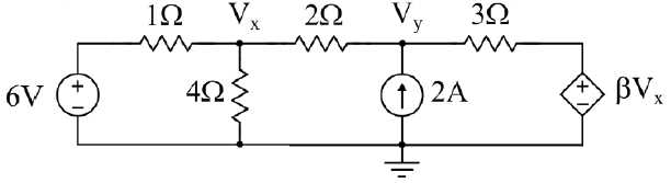
Q.16 In the given circuit, for voltage Vy to be zero, the value of should be ____ (Round off to 2 decimal places).
Ans: -3.30 to -3.20
Solution:- We will solve this problem by considering some steps:-
Step-I :- Applying KCL to the node Vx
frac{V_{x}-6}{1}+frac{V_{x}}{4}+frac{V_{x}-V_y}{2}=0Solving this,
4Vx-24+Vx+2Vx-2Vy = 0
7Vx – 2 Vy = 24 —(i)
When Vy=0
7Vx = 24
Vx=24/7
Step-II :- Applying KCL at node 2 i.e. Vy
frac{V_{y}-V_x}{2}+frac{V_{y}-beta {V_x}}{3}=23Vy-3Vx+2Vy-2βVx = 12 [/katex]
5Vy – (3+2β)Vx = 12
Vy=0
-(3+2beta )frac{24}{7}=12Solving equation we get value of β= frac{-13}{4} = -3.25
β= -3.25
The value of β is -3.25 .
Q.17 A1mu C point charge is held at the origin of a cartesian coordinate system. H a second point charge of 10mu C is moved from (0, 10, 0) to (5, 5, 5) and subsequently to (5, 0, 0), then the total work done is ____ mJ. (Round off to 2 decimal places).
Take frac1{4pivarepsilon_0}=9times10^9 in SI units. All coordinates are in meters.
Ans: 8.90 to 9.10
Solution:- Let Q1 be the charge 1 = 1 μC and Q2 be the charge 2 = 10 μC
AS it is given that charge moved from (0, 10, 0) to (5, 5, 5) and subsequently to (5, 0, 0). As charge is moving from one point to another means there is work done.
We have q1= 1 μC, q2 = 10 μC
Assume r1 is the distance between the two point charges placed at (0,0,0) and other at (0,10,0)
r1=10 m
Let r2 is the distance betwee the two point charges one placed at origin (0,0,0) and other at (5,0,0) )
r2=5 m
Total work done is given by,
W=kq_{1}q_{2}left ( frac{1}{r_{2}}-frac{1}{r_{1}} right ) W=9 times 10^9 times 10^-11 left ( frac{1}{5}-frac{1}{10} right )W= 9 mJ
Q.18 The power input to a 500 V, 50 Hz, 6-pole, 3-phase induction motor running at 975 RPM is 40 kW. The total stator losses are 1 kW. If the total friction and windage losses are 2.025 kW, then the efficiency is ___ %.
Ans: 89.50 to 90.50
Solution:- Given input 40 kW , V= 500 V , P=6 , f=50 Hz , N=975 rpm ,
The total Stator losses are = 1 kW
Total friction and windage losses = 2.025 kW
Stator output is given by
Stator output = Power input – Stator loss = 40-1= 39 kW
%s= frac{N_s-N}{N_s} = frac{1000-975}{1000}= 0.025 %
%s = 0.025%
The rotor o/p = Rotor i/p x (1-s)
= 39(1-0.025) = 38.025 kW
The motor output = Rotor o/p – (Total friction and Windage losses)
= 38.025 – 2.025 = 36 kW
Efficiency is given by, η= frac{Motor ;output}{Motor ; input}times 100
η = frac{36}{40}times 100
η =90 %
The efficiency is 90%.
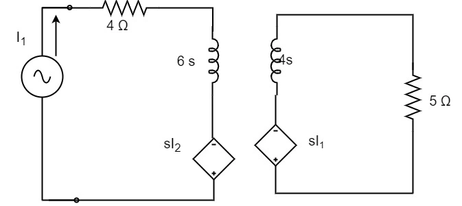
Q. 19 An alternator with internal voltage of 1angledelta_1 and synchronous reactance of 0.4 p.u is connected by a transmission line of reactance 0.1 p.u to a synchronous motor having synchronous reactance 0.35 p.u and internal voltage of 0.85angledelta_2 p.u. If the real power supplied by the alternator is 0.866 p.u, then left(delta_1-delta_2right) is ____ degrees. (Round off to 2 decimal places.) (Machines are of non-salient type. Neglect resistances.)
Ans: 59.00 to 61.00
Solution:- Given real power in (p.u) P = 0.866
Xd=0.4 p.u
XL= 0.1 p.u
Xm= 0.35 p.u
Total reactance (X) = Xd+XL+Xm = 0.4 + 0.1 + 0.35 = 0.85 p.u
V= 0.85 ∠δ2 p.u
E= 1 ∠δ1 pu
The real power is given by
P=frac{EVsin(delta {1}-delta {2})}{X_{eq}}0.866 = frac{1 times 0.85}{0.85} sin(delta {1}-delta {2})
sin(delta {1}-delta {2}) = 0.866
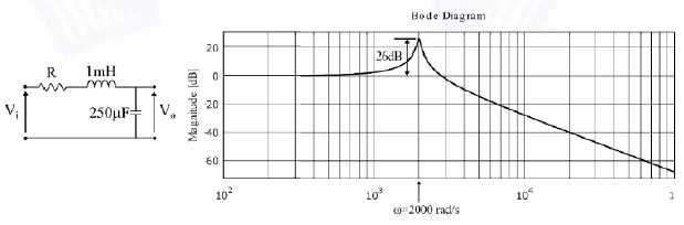
delta {1}-delta {2} = 60^oQ.20 The Bode magnitude plot for the transfer function frac{V_oleft(sright)}{V_ileft(sright)} of the circuit is as shown. The value of R is _____ Omega. (Round off to 2 decimal places.)
Ans: 0.09 to 0.11
Solution:-
Given the Bode plot and the response plot
From response plot , the value of Mr = 26 dB = 20
The formula of Resonant Peak is ,
M_{r}=frac{1}{2xi sqrt{1-xi ^{2}}}Mr = 19.95
ξ=0.025
For RL series circuit
xi =frac{R}{2}sqrt{frac{250}{1}}0.025 = frac{R}{2}sqrt{frac{250}{1}}
R=0.10 Ω
Q.21 A signal generator having a source resistance of 50Omega is set to generate a 1 kHz sinewave. Open circuit terminal voltage is 10 V peak-to-peak. Connecting a capacitor across the terminals reduces the voltage to 8 V peak-to-peak. The value of this capacitor is _____mu F. (Round off to 2 decimal places.)
Ans: 2.30 to 2.50
Solution:- The given source resistance is 50Omega ., f= 1kHz, R=50Ω
WE know that the output peak to peak voltage under open circuit condition is the source peak to peak voltage.
Peak to peak Vs=peak to peak Vo = 10 V
Therefore, The ratio of output to input is given by,
frac{V_{o}(jomega) }{V_{i}(jomega)}=frac{1}{1+jomega RC} frac{8 }{10}angle theta=frac{1} {1+jomega RC}1+jωRC = 1.25 angle theta
omega RC=sqrt{1.25^{2}-1^{2}}ωRC=0.75
Calculating the value of C
C=frac{0.75}{2000pi times 50}=2.38; mu FQ.22 A 16-bit synchronous binary up-counter is clocked with a frequency fCLK . The two most significant bits are OR-ed together to form an output Y. Measurements show that Y is periodic, and the duration for which Y remains high in each period is 24 ms. The clock frequency fCLK is _____ MHz. (Round off to 2 decimal places.)
Ans: 2.00 to 2.10
Solution:- The output Y is high for time period of 24 ms.
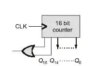
From diagram we can see that there is a 16 bit counter and Q0—-Q15 is the output.
Y=1 for 24 m sec
y=1 starts at
| Q15 | Q14 | — | Qo |
| 0000 | 0000 | 0000 | 0000 |
y=1 Ends at
| Q15 | Q14 | — | Qo |
| 1111 | 1111 | 1111 | 1111 |
Total number of states for which y=1 is high is 216
Total number of states at which y=1 is low is 214
Time is (216 – 214) = 24 msec
f=1/T = 2.05 MHz
Therefore, the frequency of the clock is 2.05 MHz
Q.23 In the BJT circuit shown, beta of the PNP transistor is 100. Assume VBE = -0.7 V. The voltage across R c will be 5 V when R is ____ kOmega. (Round off to 2 decimal places.)
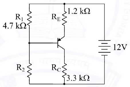
Ans: 16.70 to 17.70
Solution:- The diagram can be simplified as,

The collector current is given by,
I_{c}=frac{V}{R_C}=frac{5V}{3.3K}= 1.515 ; mAThe emitter current is IE= 1.53 mA
The base current is IB= 0.0151 mA
-12 + 1.2 x 103 x 1.53 x 10-3 + 0.7 + VB = 0
VB=9.464 V
THe current Ix is given by
I_{x}=frac{12-V_{B}}{4.7 k}=frac{1-9.464}{4.7k}=0.539 mA
And we know that,
Ix+IB=Iy
Iy= 0.5396+0.0151
Iy= 0.5546 mA
VB= 0.5546 x 10⁻³ x R2 = 9.464
Therefore,
R2= 17.06 kΩ
Q.24 In the circuit shown, the input Vi, is a sinusoidal AC voltage having an RMS value of 230Vpm20%. The worst-case peak-inverse voltage seen across any diode is _____ V. (Round off to 2 decimal places.)
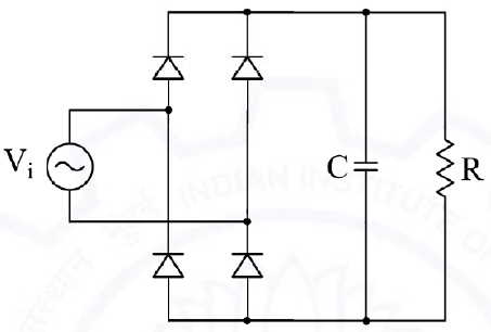
Ans: 389 to 391
Solution:- The given circuit is a full wave bridge rectifier.
Given input Vi is a sinusoidal AC voltage have RMS value of
Vrms = 230 ± 20%
The worst case peak inverse voltage is given by,
(VD)peak for worst case = (230+20%) x sqrt(2)
=left (230+230times frac{20}{100} right )times sqrt{2}=390.32; VQ.25 In the circuit shown, a 5 V Zener diode is used to regulate the voltage across load R₀. The input is an unregulated DC voltage with a minimum
value of 6 V and a maximum value of 8 V. The value of Rs is 6Omega. The Zener diode has a maximum rated power dissipation of 2.5 W. Assuming the Zener diode to be ideal, the minimum value of R0 is ______ Omega.
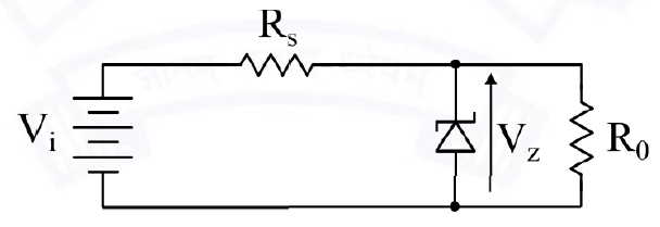
Ans: 29.00 to 31.00
Solution:- The given zener voltage is Vz=5V
For maximum power in zener
Power = VzImax
2.5 = 5 x Iman
Imax=0.5 A
As given diode is ideal so, Izmin = 0 A
The output resistance Ro= Vz/Io
Because Vz is constant, to get minimum value of Ro, Io must be maximum.
frac{V_{zmin}-V_{z}}{R_{s}}=I_{Lmax} frac{6-5}{6}=I_{Lmax}ILmax = 1/6 A
R_{omin}=frac{V_{z}}{I_{Lmax}}=frac{5}{1/6}=30; OmegaQ.26 — Q.37 Multiple Choice Question (MCQ), carry TWO mark each (for each wrong answer: — 2/3).
Q.26 In the open interval (0,1) , the polynomial p(x) = x4 – 4x3 + 2 has
a) two real roots
b) one real root
c) three real roots
d) no real roots
Ans: b) one real root
Solution:- The given polynomial is p(x) = x4 – 4x3 + 2
x4+2=4x3
Consider two function
Let first function be f1(x) = x4+2
f2(x) = 4x3
Now, using Intermediate value theorem
p(0) = 0-0+2 = 2
p(1) = 1-4+2 = -1
As,
p(0)>0 –(i)
p(1) <0 –(ii)
From eq.(i) and (ii) there exist value ‘x’ between ‘0’ and 1 where p(x)=0
Hence, in open interval (0,1) the polynomial p[(x) has one real root.
So, only one real root exists in (0,1)
Q.27 Suppose the probability that a coin toss shows “head” is p , where 0<p<1. The coin is tossed repeatedly until the first “head” appears. The expected number of tosses required is
a) p/(1-p)
b) (1-p)/p
c) 1/p
d) 1/p2
Ans: c) 1/p
Solution:- Let P(H) = p , and x= Number of tosses
The probability that a coin toss ‘head’ is p , where 0<p<1
The coin is tossed repeatedly until first head appears
| x | 1 | 2 | 3 | 4 | 5 |
| P(x) | p | (1-p)p | (1-p)2p |
= p +2p(1-p)+(1-p)2+…
E[X] = p[1+2(1-p)+3(1-p)2+..]
= p[1-(1-p)]-2 = 1/p
So, option (c) is correct.
Q.28 Let (-1 – J), (3-J), (3 +j) and (-1+ y) be the vertices of a rectangle C’ in the complex plane. Assuming that C is traversed in counter-clockwise direction, the value of the contour integral oint_cfrac{dz}{z^2left(z-4right)} is
a) jpi/2
b) 0
c) -jpi/8
d) jpi/16
Ans: c) -jpi/8
Solution:- The given contour integral is
oint_cfrac{dz}{z^2left(z-4right)}Taking denominator
z2(z-4)=0
z=0,4
z=0 is pole of order m=2 lies inside contour ‘c’
z=4 is pole of order m=1 lies outside’c’
oint _{C}frac{dz}{z^{2}(z-4)}=2pi j ; Resf(0) Res; f(0)=frac{1}{2-1!}left ( frac{d^{2-1}}{dz^{2-1}}left ( z^{2} frac{1}{z^{2}(z-4)}right ) right )Res f(0) = frac{d}{dz}left [ frac{1}{z-4} right ]_{z=0}=-frac{1}{16}
oint _{C}frac{dz}{z^{2}(z-4)}=2pi jleft ( frac{-1}{16} right )=frac{-jpi }{8}The value of contour integral is -jpi/8
so, option (c) is correct
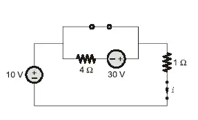
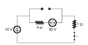
Q.29 In the circuit, switch ‘S’ is in the closed position for a very long time. If the switch is opened at time t = 0, then iL(t) amperes, for tgeq0 is
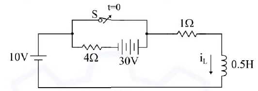
a) 8 e-10t
b) 10
c) 8+2e-10t
d) 10(1-e-2t)
Ans: c) 8+2e-10t
Solution:- Consider two cases
Case-I :- When t=0-
iL(0-) = 10/1 = 10 A
Case-II :- For t>0
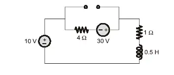
Case-III :- At t=∞
i(∞)=40/5 = 8 A
Now, given the equivalent resistance

i(t) = 8 + [10-8] e-t/0.1
i(t) = 8 + 2e-10t A
So, option (c) is correct.
Q.30 The input impedance, Zin(s), for the network shown is
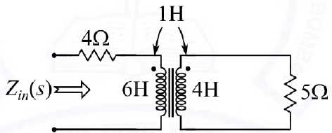
a) frac{23s^2+46s+20}{4s+5}
b) 6s+4
c) 7s+4
d) frac{25s^2+46s+20}{4s+5}
Ans: a) frac{23s^2+46s+20}{4s+5}
Solution:- The circuit in laplace s-domain is given as,
Applying KVL to the input loop
V1(s) = (4+6s) I1(s) + sI2(s)
Applying KVL in the output loop
I2(s)[5+4s] +sI1(s) = 0
frac{V_{1}}{I_{1}}=frac{(4+6s)(4s+5)-s^{2}}{4s+5} Z_in= frac{V_{1}}{I_{1}}=frac{24s^{2}+30s+16s+20-s^{2}}{4s+5}=frac{23s^{2}+46s+20}{4s+5}So, option (a) is Correct.
Q.31 The causal signal with z-transform Z2(Z-a)-2 is (u [n] is the unit step signal)
a) a2nu[n]
b) (n+1)anu[n]
c) n-1anu[n]
d) n2anu[n]
Ans: b) (n+1)anu[n]
Solution:- Causal signals ar signals that are zero for all negative time. A sysetm is said to be causal if its output depends upon present and past inputs, and does not depend upon future input.
We know that
nanu(n) = frac{az}{(z-a)^2}
From standard Z-transform
frac{1}{a}na^{n}u(n)Leftrightarrow frac{z}{(z-a)^{2}}The given signal is causal, therefore
f(n)=nan-1 u(n) = frac{z}{(z-a)^{2}} = F(z)
So, option(b)is the correct answer.
Q.32 Let f(t) be an even function, i.e. f(-t)=f(t) for all t. Let the Fourier transform of f(t) be defined as Fleft(omegaright)=intlimits_{-infty}^infty fleft(tright)e^{-jomega t}dt. Suppose frac{dFleft(omegaright)}{domega}=-omega Fleft(omegaright) for all omega, and F(0)=1. Then
a) f(0)<1
b) f(0)>1
c) f(0)=1
d) f(0)=0
Ans: a) f(0)<1
Solution: A signal is called even when f(t) = -f(t)
Given function is even,
frac{dFleft(omegaright)}{domega}=-omega Fleft(omegaright)We know the differentiation property,
tf(t)=frac{jdF(omega )}{df}Taking j on both the sides
frac{jdF(t)}{df} =-t f(t) —(2)
We can see from both the equation that f(t) is the change of Gaussian function
f(t) = frac{1}{sqrt{2pi }}e^{-frac{t^{2}}{2}} –(iii)
From eq.(iii)
We see,
frac{1}{2pi }e^{frac{-t^{2}}{2}}leftrightarrow e^{frac{-omega ^{2}}{2}}f(t) = frac{1}{2pi }e^{frac{-t^{2}}{2}}
f(0) = frac{1}{2pi}
f(0)=0.159
f(0) < 1
So, option (a) is correct.
Q.33 In a single-phase transformer, the total iron loss is 2500 W at nominal voltage of 440 V and frequency 50 Hz. The total iron loss is 850 W at 220 V and 25 Hz. Then, at nominal voltage and frequency, the hysteresis loss and eddy current loss respectively are
a) 1600 W and 900 W
b) 900 W end 1600 W
c) 250 W and 600 W
d) 600 W and 250 W
Ans: b) 900 W end 1600 W
Solution: Given data is that the total iron loss i.e. Wi1 = 2500 W , V= 440 V , f=50 Hz
The another iron loss is Wi2=850 W at V= 220 V , 25 Hz
We know that in transformer iron loss has two components i.e. Hysteresis loss (Ph) and Eddy current loss (Pe).
Wi = Wh + We
Pi= khfBmn + kef2Bm2 —(i)
As Wh ∝ f
Wh = af
kh and ke are loss coefficient constant.Bm is the maximum value of flux density
Wi= af + bf2
2500 = 50a+2500b —(i)
850 = 25a+625 b —(ii)
Solving simultaneously we get value of a= 18, b=0.64
iron loss at 50 50 Hz
Hysteresis loss (Ph) = af = 18 x 50 = 900 W
Eddy current loss (Pe) = bf2 = 0.64 x 2500 = 1600 W
So, option (b) is correct.
Q.34 In the figure shown, self-impedances of the two transmission lines are 1.5j p.u each, and Zm = 0.5j p.u is the mutual impedance. Bus voltages shown in the figure are in p.u. Given that delta>0, the maximum steady-state real power that can be transferred in p.u from Bus-1 to Bus-2 is
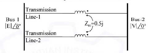
a) left|Eright|left|Vright|
b) frac{left|Eright|left|Vright|}2
c) 2left|Eright|left|Vright|
d) frac{3left|Eright|left|Vright|}2
Ans: a) left|Eright|left|Vright|
Solution: The self impedances of two lines are 1.5j p.u and Zm=0.5 j p.u.
The equivalent inductance is given by,
L_{eq}=frac{L_{1}L_{2}-M^{2}}{(L_{1}-L_{2}-2M)}The equivalent reactance is given by,
X_{eq}=frac{1.5times 1.5-0.5^{2}}{1.5+1.5-2times 0.5}=1Therefore, the maximum steady state real power that can be transferred from one bus to another is given by,
P_{max}=frac{|E||V|}{1}=E|V|Q.35 A 3-Bus network is shown. Consider generators as ideal voltage sources. If rows 1, 2 and 3 of the YBus matrix correspond to Bus 1, 2 and 3, respectively, then YBus of the network is
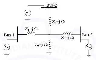
a) begin{bmatrix}-4j&j&j\j&-4j&j\j&j&-4jend{bmatrix}
b) begin{bmatrix}-4j&2j&2j\2j&-4j&2j\2j&2j&-4jend{bmatrix}
c) begin{bmatrix}-frac34j¼j¼j\frac14j&-frac34j¼j\frac14j¼j&-frac34jend{bmatrix}
d) begin{bmatrix}-frac12j¼j¼j\frac14j&-frac12j¼j\frac14j¼j&-frac12jend{bmatrix}
Ans: c) begin{bmatrix}-frac34j¼j¼j\frac14j&-frac34j¼j\frac14j¼j&-frac34jend{bmatrix}
Solution: From the given diagram we can get value as
V1=j1i1+j1(i1+i2+i3)
V1=2i1+ji2+ji3
V2=ji1+2ji2+ji3
V3=ji1+ji2+2ji3
Putting these values in matrix form.
begin{bmatrix}V_{1}\V_{2}\V_{3}\end{bmatrix}=begin{bmatrix}2j & j & j j &2j & j\j & j & 2jend{bmatrix}begin{bmatrix}i_{1}\i_{2}\i_{3} end{bmatrix}Zbus = begin{bmatrix}2j & j & jj &2j & j\j & j & 2jend{bmatrix}
Y_{bus}=begin{bmatrix}frac{-3j}{4} & frac{j}{4} & frac{j}{4}\frac{j}{4}& frac{-3j}{4} & frac{j}{4}\frac{j}{4} &frac{j}{4} & frac{-3j}{4}end{bmatrix}Therefore, option (c) is correct answer.
Q.36 Suppose IA , IB and IC are a set of unbalanced current phasors in a three- phase system. The phase-B zero-sequence current I_{Bo}=0.1angle0^op.u. If phase-A current I_A=1.1angle0^op.u and phase-C current I_C=left(1angle120^o+0.1right)p.u, then IB in p.u is
a) 1angle240^0-0.1angle0^o
b) 1.1angle240^0-0.1angle0^o
c) 1.1angle120^0+0.1angle0^o
d) 1angle-120^0+0.1angle0^o
Ans: d) 1angle-120^0+0.1angle0^o
Solution: The curent at Bo is given by,
I_{Bo}=frac{1}{3}(I_{A}+I_{B}+I_{C}) 0.1=frac{1}{3}(1.1angle 0+I_{B}+1angle 120^{o}+0.1)IB= 0.3-1.1∠0-0.1- 1∠120o
IB= -0.9 – 1∠120o
IB=0.1+1∠240o
IB=1∠-120o+0.1∠0o
So, option (d) is the correct answer.
Q.37 A counter is constructed with three D flip-flops. The input-output pairs are named (Do, Qo), (D1, Q1), and (D2, Q2), where the subscript 0 denotes the least significant bit. The output sequence is desired to be the Gray-code sequence 000, 001, 011, 010, 110, 111, 101, and 100, repeating periodically. Note that the bits are listed in the Q2 Q1 Qo format. The combinational logic expression for D1 is
a) Q2Q1Q0
b) Q_2Q_0+Q_1{overline Q}_0
c) {overline Q}_2Q_0+Q_1{overline Q}_0
d) Q_2Q_1+;{overline Q}_2{overline Q}_1
Ans: c) {overline Q}_2Q_0+Q_1{overline Q}_0
Solution:
The truth table for present state and next state are as follows.
| Present State | Next State | |||||||
| Q2 | Q1 | Qo | Q2+ | Q1+ | Qo+ | D2 | D1 | Do |
| 0 | 0 | 0 | 0 | 0 | 1 | 0 | ||
| 0 | 0 | 1 | 0 | 1 | 1 | 1 | ||
| 0 | 1 | 0 | 0 | 1 | 0 | 1 | ||
| 0 | 1 | 1 | 1 | 1 | 0 | 1 | ||
| 1 | 0 | 0 | 1 | 1 | 1 | 1 | ||
| 1 | 0 | 1 | 1 | 0 | 1 | 0 | ||
| 1 | 1 | 0 | 1 | 0 | 0 | 0 | ||
| 1 | 1 | 1 | 0 | 0 | 0 | 0 | ||
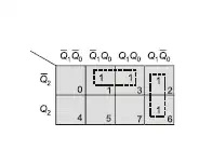
The combination logic expression for D1 is
D1= barQ_2Q_o + Q1barQ_o
Q.38 — Q.55 Numerical Answer Type (NAT), carry TWO mark each (no negative marks).
Q.38 Let A be a 10 x 10 matrix such that A5 is a null matrix, and let I be the 10 x 10 identity matrix. The determinant of A + I is ____ .
Ans: 1 to 1
Solution: Given data is A5 is a null matrix of order 10
I is the identity matrix of 10 x 10
A5=0 (As it is the null matrix)
We know that, Ax=λx
A5x = λ5x (here x is not equal to 0)
λ5=0
λ=0
The Eigen values of A+I is λ+1
Eigen values of IA=1
Hence | A+I | = Product of eigen values = 1 x 1 x 1x– 10 times
Therefore, the value of A+λ = 1
Q.39 A three-phase balanced voltage is applied to the load shown. The phase sequence is RYB. The ratio frac{left|I_Bright|}{left|I_Rright|} is ______ .
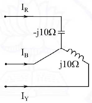
Ans: 1 to 1
Solution:
The given circuit is
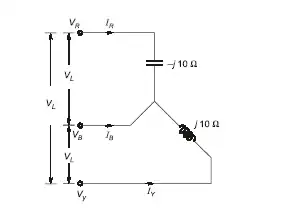
Now let us find line voltage
I_{R}=frac{V_{RB}}{-j10}=frac{V_{L}angle -60^{o}}{-j10}=frac{V_{L}}{10}angle 30^{o} I_{Y}=frac{V_{YB}}{-j10}=frac{V_{L}angle -120^{o}}{-j10}=frac{V_{L}}{10}angle 150^{o}IB= -(IR+IY)= frac{V_{L}}{10}-angle 90^{o}
The magnitude of IR and IB is given by
left | frac{I_{B}}{I_{R}} right |=1Q.40 In the given circuit, for maximum power to be delivered to RL, its value should be Omega. (Round off to 2 decimal places.)

Ans: 1.40 to 1.42
Solution: We know that the maximum power transfer theorem states that the maximum power transfer from the AC network to the load when the load impedance is equal to the complex conjugate of Thevenin’s equivalent impedance.
Zth = R || (XL+Xc) = 2 || j2 = frac{2times j2}{2+j2}=frac{j2}{1+j1}
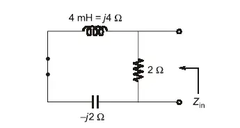
For maximum power trasnfer , RL = |Zth| = sqrt{R_{th}^{2}+X_{th}^{2}}
R_{L}=|Z_{th}|=frac{sqrt{2^{2}}}{(1^{2}+12^{2})}=sqrt{2}; OmegaSo, the value of RL = 1.414 Ω
Q.41 One coulomb or point charge moving with a uniform velocity 10;widehat X m/s enters the region xgeq0 having a magnetic flux density overrightarrow B=left(10y;widehat x+10x;widehat y+10;widehat zright)T. The magnitude of force on the charge at x=0+ is _____ N. ( widehat X,;widehat Y;and;widehat Z are unit vectors along a-axis, y-axis, and z-axis, respectively.)
Ans: 100 to 100
Solution: Given the overrightarrow B=left(10y;widehat x+10x;widehat y+10;widehat zright)
overrightarrow{v}= 10hat{x}The force on a moving charge with velocity overrightarrow{v} velocity due to the magnetic field is given by,
overrightarrow{F}=Q(overrightarrow{v}times overrightarrow{B}) = 1[ 10hat{x} times left(10y;widehat x+10x;widehat y+10;widehat zright)[/latex]</p> <div style="height:10px" aria-hidden="true" class="wp-block-spacer"></div> <p>[katex] = 10(10x)hat{z}+10(10)(-hat{y})= 100x hat{z}-100hat{y}
overrightarrow{F}|_{x=0}=-100hat{y}overrightarrow{F}|_{x=0}=sqrt{(-100)^{2}}=100 Newton
So, the magnitude of force on the charge at x=0+ is 100 N
Q.42 Consider a large parallel plate capacitor. The gap d between the two plates is filled entirely with a dielectric slab of relative permittivity 5. The plates are initially charged to a potential difference of V volts and then disconnected from the source. H the dielectric slab is pulled out completely, then the ratio of the new electric field E2 in the gap to the original electric field E1 is _____.
Ans: 5 to 5
Solution: Given that the plates are initially charged at a potential difference of V volts. In general, Q=CV
Consider two cases, where charge Q is constant, when voltage source is removed.
Case-I :- (When (Q1=Q, V1=V)
Charge is given by,
Q1=C1V1
Q=frac{varepsilon {o}5A}{d}V{1}=5left ( frac{epsilon {o}A}{d} right )V{1} ----(i)
Case-2 :- When Q2=Q, V2
Q2=CV2
Q=frac{varepsilon {o}1A}{d}V{1}=left ( frac{epsilon {o}A}{d} right )V{2} ----(ii)
Equation (i) = Equation (ii)
5left ( frac{epsilon {o}A}{d} right )V{1} = left ( frac{epsilon {o}A}{d} right )V{2}
5V1=V2
frac{V_2}{V_1} = 5
E_{1}=frac{V_{1}}{d}, E_{2}=frac{V_{2}}{d}Taking ratio of E2 / E1
frac{E_{2}}{E_{1}}=frac{V_{2}/d}{V_{1}/d}=frac{V_{2}}{V_{1}}Putting value of V2/V1 in E2/E1 we get
E2/E1= 5
The ratio of the new electric field E2 in the gap to the original electric field E1 is 5.
Q.43 Consider a continuous-time signal x(t) defined by x(t)=0 for left|tright|>1 and xleft(tright)=1-left|tright| forleft|tright|leq1. Let the Fourier transform of X(t) be defined as Xleft(omegaright)=intlimits_{-infty}^infty xleft(tright)e^{-jomega t}dt. The maximum magnitude of Xleft(omegaright) is _______.
Ans: 1 to 1
Solution: Given continuous time signal is x(t)=0 for |t| >1
x(t) = 1 - |t| for |t| ≤ 1
The waveform can be drawn as,
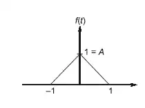
Here the given function is a triangular function
The fourier transform is given by,
X(ω)= ATsa2 frac{omega; T }{2}
As A=1, τ=1
X|(ω)|peak=X(0) = sa2 frac{0}{2} =1
Therefore, the peak value of sampling function occurs at ω=0.
Peak value =1
The maximum magnitude of X(ω) is 1.
Q.44 A belt-driven DC shunt generator running at 300 RPM delivers 100 kW to a 200 V DC grid. It continues to run as a motor when the belt breaks, taking 10 kW from the DC grid. The armature resistance is 0.025 Omega, field resistance is 50 Omega , and brush drop is 2 V. Ignoring armature reaction, the speed of the motor is ______ RPM. (Round off to 2 decimal places.)
Ans: 273.00 to 277.00
Solution: The EMF equation of DC machine is given by E=frac{Pphi ZN}{60 A}
Consider three cases,
Case-I :- When machine acts as a generator
P=VIL = 100 kW
Terminal voltage = 200 V
I_{L}=frac{100times 10^{3}}{200}=500The shunt current is given by,
Ish = V/Rsh = 200/50 = 4 A
Ia1 = IL+Ish = 500 + 4= 504 A
N1= 300 rpm
Armature resistance Ra= 0.025 Ω
The generated emf is given by,
Eg= V+IaRa + Brush drop = 200 + 504(0.025) + 2 V = 214.6 V
Case-II :- When machine acts as a motor
Input power = P = VIL = 10 kW
Terminal voltage (V) = 200 V
I=frac{10000}{200}=50 AIf= 4A , Ia= IL-If = 46 A
Eb = V- IaRa - Brush drop = 200 - 46(0.025) -2 = 196.85 V
We know that Eb ∝ N
frac{E_{g}}{E_{b}}=frac{N_{1}}{N_{2}} frac{214.6}{196.85}=frac{300}{N_{2}}N2=275.19 RPM
The speed of the motor is 275.18 RPM
Q.45 An 8-pole, 50 Hz, three-phase, slip-ring induction motor has an effective rotor resistance of 0.08 f per phase. Its speed at maximum torque is 650 RPM. The additional resistance per phase that must be inserted in the rotor to achieve maximum torque at start is ______ Omega. (Round off to 2 decimal places.) Neglect magnetizing current and stator leakage impedance. Consider equivalent circuit parameters referred to stator.
Ans: 0.50 to 0.54
Solution: It is given that maximum Torque is 650 RPM. P=8, f= 50 Hz
The slip is given by, %s=frac{N_{s}-N}{N_{s}}=frac{750-650}{750}=0.133
In general, s_{m}=frac{R_{2}}{X_{2}}
X_{2}=frac{R_{2}}{s_{m}}=frac{0.008}{0.133}=0.601; OmegaR2= 0.08 Ω , X2= 0.601 Ω
We know the condition of maximum torque
R2=X2
R2+ r = X2
r = 0.601-0.08 = 0.521
So, the additional resistance per phase that must be inserted in the rotor toachieve maximum torque at starting is 0.521 Ω.
Q.46 Consider a closed-loop system as shown. G_Pleft(sright)=frac{14.4}{sleft(1+0.1sright)} is the plant transfer function and Gc(S) = 1 is the compensator. For a unit-step input, the output response has damped oscillations. The damped natural frequency is ______ rad/s. (Round off to 2 decimal places.)
Ans: 10.80 to 11.00
Solution:
Given function is G_Pleft(sright)=frac{14.4}{sleft(1+0.1sright)}
The transfer function of the system is given by,
frac{C(s)}{R(s)}=frac{G(s)}{1+G(s)H(s)} frac{C(s)}{R(s)}=frac{frac{14.4}{s(1+0.1s)}}{1+frac{14.4}{s(1+0.1s)}}R(s) = s2+10s+144
Comparing it with the standard equation
frac{C(s)}{R(s)}=] frac{omega {n}}{s^{2}+2xi omega {n}+omega _{n}^{2}}FRom this we get,
ωn2=144
ωn=12
2ξωn=10
ξ=10/24=5/12
Then the damped natural frequency is given by,
omega {d}=omega {n}sqrt{1-xi ^{2}}=12sqrt{1-frac{10}{24}^{2}}= 10.91 rad/sec
The damped natural frequency is 10.91 rad/sec
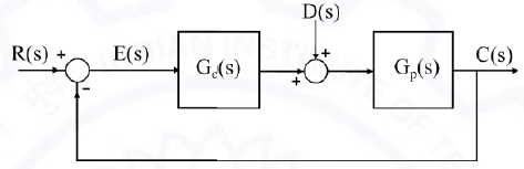
Q.47 In the given figure, plant G_Pleft(sright)=frac{2.2}{left(1+0.1sright)left(1+0.4sright)left(1+1.2sright)} and compensator. G_cleft(sright)=Kleft(frac{1+T_1s}{1+T_2s}right). The external disturbance input is D(s). It is desired that when the disturbance is a unit step, the steady-state error should not exceed 0.1 unit. The minimum value of K is ______. (Round off to 2 decimal places.)
Ans: 9.50 to 9.60
Solution:
The steady state error is given by,
e_{ss}=lim_{srightarrow 0}left ( frac{sR}{1+G_{c}G_{p}}-frac{sDG_{p}}{1+G_{c}G_{p}} right )Given that R(s) =0 and D(s) =1/s
e_{ss}=lim_{srightarrow 0}left ( frac{2.2}{1+2.2K}=0.1 frac{2.2}{1+2.2K}leq 0.1Kmin= 9.54
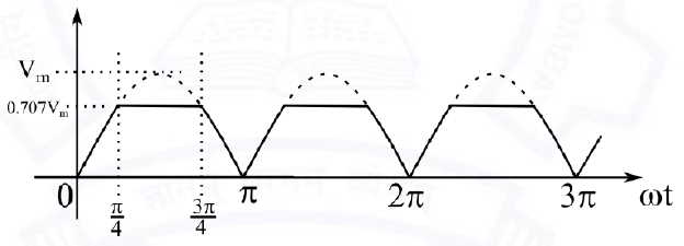
Q.48 The waveform shown in solid line is obtained by clipping a full-wave rectified sinusoid (shown dashed). The ratio of the RMS value of the full- wave rectified waveform to the RMS value of the clipped waveform is _____. (Round off to 2 decimal places.)
Ans: 1.20 to 1.23
Solution:
The given waveform is
The RMS value of clipping (V) waveform over the period from 0 to π is
V=sqrt{frac{1}{pi }left [ int_{0}^{pi /4} V_{m}^{2}sin^{2}(t)dt+right ]+left [ int_{ pi/4}^{ 3pi/4} frac{V_{m}}{sqrt{2}}^{2}dt+ right ]+left [ int_{ 3pi/4}^{ pi} V_{m}^{2}sin^{2}dt right ]} V=sqrt{frac{1}{pi }left [ 2times int_{0}^{pi /4} V_{m}^{2}sin^{2}(t)dt+right ]+left [ int_{ pi/4}^{ 3pi/4} frac{V_{m}}{sqrt{2}}^{2}dt+ right ] V=sqrt{left [ frac{2V_{m}^{2}}{2} int_{0}^{pi /4}(1-cos(2)dt+frac{2V_{m}^{2}}{2}int_{pi /4}^{3pi /4}dtright ]} V=frac{V_{m}}{sqrt{pi }}sqrt{frac{pi }{4}+frac{1}{2}+frac{pi }{4}}V=0.584 Vm
WE know that the RMS value of full-wave rectified waveform Vfw=70.7 % of the maximum value.
Vfw= 0.707 Vm
The ratio of the RMS value of the full wave rectified waveform to RMS value of clipped waveform is
frac{V_{fw}}{V}=frac{0.707V_{m}}{0.584V_{m}}=1.21Q.49 The state space representation of a first-order system is given as
dot X=X+u
y=x
where, x is the state variable, u is the control input and y is the controlled output. Let u= -Kx be the control law, where K is the controller gain. To place a closed-loop pole at -2, the value of K is ______.
Ans: 1 to 1
Solution:
The given state space representation is
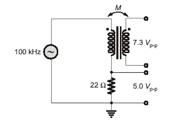
dot X=X+udot X=-x-Kx=x(-kI-I)[/katex] </p> <p>The characteritics equation of the given first -order system is</p> <p>|sI+KI+I|=0</p> <p>|(s+1+K)I|=0</p> <p>s+1+K=0</p> <p>s=-1-K</p> <p>-2=-1-K</p> <p>K=1</p> <p>So, the value of K is 1. </p> <hr class="wp-block-separator has-alpha-channel-opacity is-style-wide" /> <p>Q.50 An air-core radio-frequency transformer as shown has a primary winding and a secondary winding. The mutual inductance M between the windings of the transformer is _______ [latex]muH. (Round off to 2 decimal places.)
Ans: 50.00 to 52.00
Solution: Here the given voltage source is 100 kHz
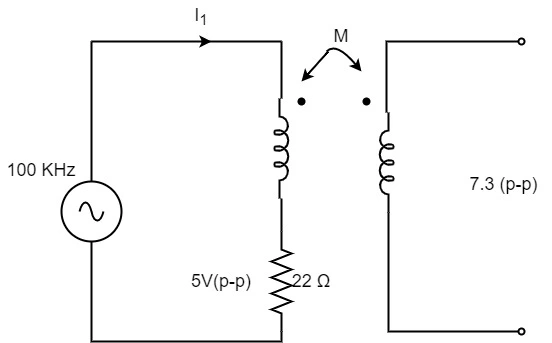
We know that the when two coils are placed close to each other , a change in current in the first coil produces a chnage in magnetic f;lux, which cuts not only the coil itself but also the second coil as well.Tthere is mutual inductance between the two coils. Let M is the mutual inductance between two coils.
The current is given by,
I I_1=frac{V}{R}(p-p) =frac{5}{22}(p-p)[/katex]
The output voltage is given by, Vo=jωMI1 = 7.3
= (2π x 10 x 103) x M x frac{5}{22}
M= 51.10 μH
The mutual inductance between the windings of the transformer is 51.10 μH
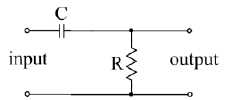
Q.51 A 100 Hz square wave, switching between 0 V and 5 V, is applied to a CR high-pass filter circuit as shown. The output voltage waveform across the resistor is 6.2 V peak-to-peak. If the resistance R is 820Omega, then the value C is ______ muF. (Round off to 2 decimal places.)
Ans: 12.30 to 12.60
Solution: The given circuit is
Applying KVL inthe input loop
Vi = Vc + Vo
Vo = Vi - Vc
In a 100 Hz square wave there are two cycles
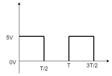
In first half cycle, consider the range 0 < t < T/2
Here capacitor charges to maximum value of 5 V
Vo = 5 - Vc
In second half cycle, consider the range T/2 < t < T
Input voltage in this range is 0
So, Vi= 0V , Vo = - Vc
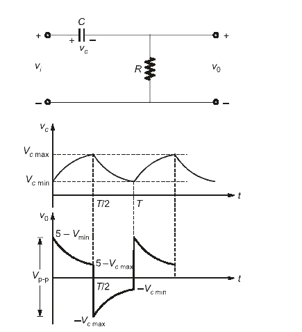
The peak to peak output voltage across the resistor is given by,
Vo(p-p) = (5- Vcmin) - (-Vcmax)
6.2 = 5 + Vcmax - Vc min
Vcmax - Vcmin = 1.2 --(i)
i) For first half cycle, i.e. from range 0 < t< T/2
Vc(0+)= Vc(0-) = Vc(0) = Vcmin
Vc(∞) = 5 V
Vc(t) = Vc(∞) + [Vc(0+)-Vc(∞)] e-t/τ
Vc(t) = 5 + [vcmin -5] e-t/2τ = Vcmax
Vcmax = 5[1-e-T/2τ) + Vcmine-T/2τ ---(ii)
Now for range T/2 < t < T
In this half cycle, the capacitor starts discharging in an exponential manner and at t=T , it becomes Vcmin
Vc = Vcmin = Vcmaxe-T/2 τ --(iii)
From eq.(i) (ii) and (iii)
5[1-e-T/2T]+Vcmine-T/2τ - Vcmax e-T/2τ = 1.2
Solving this we get
5[1-e-T/2T]+(Vcmin-Vcmax)e-T/2τ =1.2
5[1-e-T/2T]+ (-1.2) e-T/2T]=1.2
5-6.2 e-T/2T= 1.2
e-T/2T = 3.8/6.2 = 0.6819
Tasking log on both sides,we get
-T/2τ =0.4895
T=1/f = 1/100 sec
τ= RC = 820 x C
frac{1}{10times 2times 820times C}=0.4895C= 12.46 μF
The value of C is 12.46 μF
Q.52 A CMOS Schmitt-trigger inverter has a low output level of 0 V and a high output level of 5 V. It has input thresholds of 1.6 V and 2.4 V. The input capacitance and output resistance of the Schmitt-trigger are negligible. The frequency of the oscillator shown is _____ Hz. (Round off to 2 decimal places.)
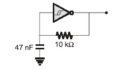
Ans: 3150.00 to 3170.00
Solution: Consider two cases :-

Case-I :- When the inverter is charging mode, and t = t1
Vc(t) = Vcfinal + [Vinitial - Vc'final ] e-t/RC
Vc(t)= 5 + (1.6 -5)e-t/RC
= 5 - 3.4 e-t/RC
Vc(t) = 2.4 V
2.4 = 5 - 3.4 e-t/RC
3.4 e-t1/RC=2.6
t_{1}=lnleft ( frac{3.4}{2.6} right )RC = 0.268 xRCCase-II :- When the inverter is in discharging mode and t=t2
Vc(t) = 0+(2.4-0) e-t/TC
Vc(t) = 2.4e-t/RC
Vc(ta) = 1.6 V
1.6 = 2.4e-t2/RC
t_{2}=lnleft ( frac{2.6}{21.6} right )RC = 0.405 xRCNow let us calculate the total time
T = t1+t2
(0.268 + 0.405) RC
T = 0.673 RC
Calculating the frequency of the oscillator
f=frac{1}{T}=frac{1}{0.673times 10^{4}times 47times 10^{-9}}=3157.46The frequency of the oscillator is 3157.46 Hz
Q.53 Consider the boost converter shown. Switch Q is operating at 25 kHz with a duty cycle of 0.6. Assume the diode and switch to be ideal. Under steady-state condition, the average resistance Rin as seen by the source is Omega. (Round off to 2 decimal places.)
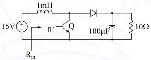
Ans: 1.55 to 1.65
Solution: Boost converter is a switch mode DC to DC converter where output is greater than the input voltage. It is also called as step up converter.
Given D=0.6, Vs=15 volt
We know that,
D=frac{T_ON}{T} frac{V_{o}}{V_{s}}=frac{1}{1-D}V_{o}=frac{V_s}{1-D} = frac{15}{1-0.6}=37.5 volt</p> <div style="height:10px" aria-hidden="true" class="wp-block-spacer"></div> <p>The current through load is given by,</p> <div style="height:10px" aria-hidden="true" class="wp-block-spacer"></div> <p>Io=[katex] frac{V_o}{R}=frac{37.5}{10} = 3.75 V
frac{V_{o}}{V_{s}}=frac{I_{s}}{I_{o}}=frac{1}{1-alpha } I_{s}=frac{I_{o}}{1-alpha }=frac{3.75}{1-0.6}=9.375 AThe average resistance Rin is given by ,
Rin = frac{V_s}{I_s}=frac{15}{9.375}=1.6 omega
Q.54 Consider the buck-boost converter shown. Switch Q is operating at 25 kHz and 0.75 duty-cycle. Assume diode and switch to be ideal. L nder steady- state condition, the average current flowing through the inductor is _____ A.
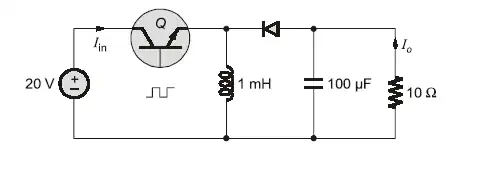
Ans: 24 to 24
Solution: Consider Vo = load voltage , Io = load current
Vdc = supply voltage
Duty cycle = D
Duty cycle = 0.75
Now let us assume continuous conduction,
V_{o}=frac{alpha V_{s}}{1-alpha }=frac{0.75times 20 V_{s}}{1-0.75 }=60 VI_o=frac{V_o}{R}=frac{60}{10} = 6 A
I_{L}=frac{I_{o}}{1-alpha }=frac{6}{1-0.75 }=24 AContinuous conduction assumption is correct
IL= 24 A
The average current flowing through inductor is 24 A.
Q.55 A single-phase full-bridge inverter fed by a 325 V DC produces a symmetric quasi-square waveform across ‘ab’ as shown. To achieve a modulation index of 0.8, the angle theta expressed in degrees should be ______. (Round off to 2 decimal places.)
(Modulation index is defined as the ratio of the peak of the fundamental component of vab to the applied DC value.)
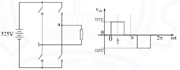
Ans: 50.00 to 52.00
Solution: Given figure is of single phase full-bridge inverter
Here, supply voltage = 325 V
Modulation index (m) = 0.8
WE know the defination of modulation index, It is the ratio of peak of the fundamental component (Vo1P) of Vab to the applied DC value.
m=frac{V01P}{V_{S}}Vo1P= frac{4V_s}{pi} sin d
here d = half of the conduction angle
Putting value of V0lP in the formula of modulation index.
m=frac{frac{4V_{s}}{pi }sin d }{V_{S}}=frac{4}{pi }sin d0.8 = frac{4}{pi }sin d
d= 38.93o
θ = 90o - d = 90o - 38.93o = 51.07o
Th angle θ should be 51.07o to achieve the modulation index of 0.8.