May 2019 Solutions
Q.1. Attempt any five of the following :- [20 M]
Q.1.a) Explain the working principle of Single Phase Transformer.
Ans. i) A transformer is a static device by means of which electric power in one circuit is transformed into electric power of same frequency in another circuit without changing frequency.
ii) It can raise or lower the voltage in a circuit but with corresponding decrease or increase in current.
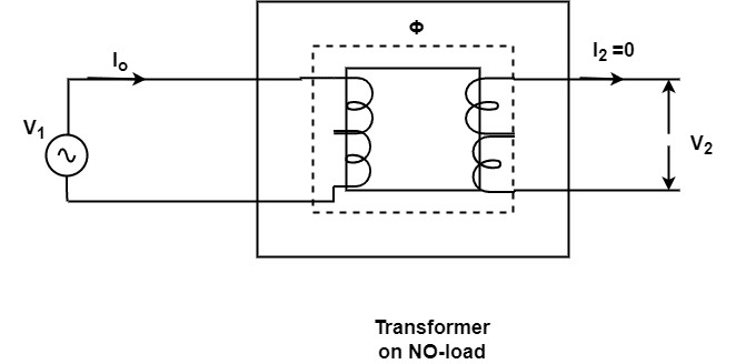
iii) The physical basic of transformer is mutual induction between two circuits linked by a common magnetic flux . In its simples form, it consists of two inductive coils which are electrically separated but magnetically linked through a path of low reluctance as shown in fig.
iv) The two coil posses high mutual inductance. If one coil is connected to a source of alternating voltage, an alternating flux is set up in the laminated core, most of which is linked with other coil in which it produces mutually induced emf. If the second coil circuit is closed, a current flows in it and so electric energy is transferred from first coil to second coil.
Q.1.b) Derive the formula to convert a star circuit into equivalent delta.
Ans.
Consider a star connected and delta connected circuit .

Let resistance be R1, R2 and R3 of the star connection and Let R12, R23, R31 are the resistances of the delta circuit.
In star connection , The resistance between terminals 1 and 2 is (R1+R2). Similarly the other terminals are also gives as inthe same way as the first one.
R_{1}+R_{2}=\frac{R_{12}\times (R_{23}+R_{31})}{R_{12}+R_{23}+R_{31}} —-(1)
R_{2}+R_{3}=\frac{R_{23}\times (R_{31}+R_{12})}{R_{12}+R_{23}+R_{31}} —-(2)
R_{3}+R_{1}=\frac{R_{31}\times (R_{12}+R_{23})}{R_{12}+R_{23}+R_{31}} —-(3)
By using this three equations and multiplying eq.(1) and (ii) , (ii) and (iii) , (iii) and (i) and adding them together and simplifying them we get
R_{12}=\frac{R_{1}R_{2}+R_{2}R_{3}+R_{3}R_{1}}{R_{3}}=R_{1}+R_{2}+\frac{R_{1}R_{2}}{R_{3}} R_{12}=\frac{R_{1}R_{2}+R_{2}R_{3}+R_{3}R_{1}}{R_{1}}=R_{2}+R_{3}+\frac{R_{2}R_{3}}{R_{1}} R_{31}=\frac{R_{1}R_{2}+R_{2}R_{3}+R_{3}R_{1}}{R_{2}}=R_{1}+R_{3}+\frac{R_{3}R_{1}}{R_{2}}Hence, the equivalent delta resistance between any two terminals is ngiven by the sum of stra resistances between those terminals plus the product of these two star resistances divide by the third star resistances.
Q.1.c) Explain the principle of operation of DC motor.
Ans.
Working principle of DC motor :- The working of DC motor is based on the principle that Whenever a current carrying conductor is placed in a magnetic field it experiences a force. An electric motor is a machine that converts an electric energy into mechanical energy.
The principle of operation of DC motor can be explained with the help of Fleming’s left hand rule .
Fleming left hand rule can be stated as , ”The direction of force produced on a current carrying conductor which is placed in a magnetic field can be determined by Fleming’s left hand rule. If the three fingers namely the fore fingers, the middle finger and the thumbs of left hand are held mutually perpendicular to each other such that if the forefinger indicates direction of magnetic flux, middle finger indicates direction of current, then thumb will indicate direction of force experienced by the conductor.
This is the principle operation of dc motor .
Q.1.d) What is necessary condition for resonance in series circuit ? Derive the expression for resonance frequency.
Ans.
A series circuit is at electrical resonance when its net reactance is zero. The frequency fr at which resonance occurs is called resonant frequency(fr).
Expression for Resonant frequency
Consider the circuit where, Resistance, capacitance and inductor is connected in series with the voltage across it.

The impedance of resonance is the resistance i.e. Z=R
As per the series resonance definition as net reactance is zero.
So XL=XC
XL= ωL
X_{C}=\frac{1}{\omega C}Putting value of XL and XC in the condition of resonance
ωL= \frac{1}{\omega C}
ω2LC=1
ω=2πfr
4π2fr2LC=1
f_{r}^{2}=\frac{1}{4\pi ^{2}LC} f_{r}=\frac{1}{2\pi \sqrt{LC}}This is the expression for resonant frequency.
Q.1.e) Find the value of R in the following circuit.

Ans.
Given :-
To Find :- R=?
Solution :-
Step-1 :- Converting the 100 V voltage source into the current source

V= IR
100 = I x 10
I= 10 A
Step-2 :- By converting the voltage source into current source the resistance , 10 Ω, 14Ω and R are connected in parallel.
So, the equivalent resistance is given by,
R_{eq}=\frac{1}{R_{1}}+\frac{1}{R_{2}}+\frac{1}{R_{3}}We will take R1= 10, R2 = 14, R3 = R
R_{eq}=\frac{1}{R_{1}}+\frac{1}{R_{2}}+\frac{1}{R_{3}}=\frac{1}{10}+\frac{1}{14}+\frac{1}{R}=0.1714+\frac{1}{R} R_{eq}=\frac{0.1714R+1}{R}As we know the ohm’s law
V= IReq
Putting value of Req in the ohm’s law
I=\frac{V}{R_{eq}} I=\frac{V}{R_{eq}}=\frac{100}{\left ( \frac{0.1714R+1}{R} \right )} 3\times \frac{R}{0.1714R+1}=1003R = 100(0.1714R+1)
3R=17.14R
-100 = 17.14R-3R+100
-100=14.14 R
R=-100/14.14
R=-7.07 Ω
(- sign indicates that resistance is in the reverse direction )
So, as resistance can’t be negative
R= 7.07 Ω
Method-II
Solution :-
Step-I :- As 10 and 14 ohms are in series so we will add these two resistances.
R=10+14 = 24

Step-2 :- By applyying ohm’s law, we get
V=IR
100 = 3 x (24+R)
100= 72+3R
28 = 3R
R= 9.33 Ω
Q.1.f) Find the current through 4 Ω resistor by source transformation in the following circuits;

Ans.
Given :-
To Find :- Current through 4 ohm resistor
Solution :-
Step-i :- Converting the 5A current source into the voltage source and taking the 2Ω in series.

Again transforming 4 V and 2 Ω

Adding 2A and 2A as they are in parallel

By current division rule
I_{4\Omega } =4\times \frac{2}{2+4}=\frac{4}{3}=1.33Q.2.a) Determine the current through 8Ω resistor in the following network by superposition theorem . [08 M]

Ans.
Step-1 :- Consider 4 V source only
Short-circuiting the 6 V source


15 || 14.8 = 7.44 Ω
Hence current through 14.8 Ω is,
I_{2}=\frac{15}{15+14.8}\times I I_{2}=\frac{15}{15+14.8}\times 0.537= 0.270 \; ASame current I2 will flow through 10 Ω and 4.8 Ω
Hence, current through 8Ω is given as,

Hemnce, current through 8 Ω is 0.162 A from A to B ,

Step 2:- Consider 6 V source only short circuiting the 4V source.


Hence, current through 8Ω is given as,

Hence, current through 8 Ω is 0.2218 A from A to B
Step-3 :- Hence using superposition theorem , current through 8 Ω is given as,

Current through 8 Ω is = 0.162 + 0.2218 = 0.3838 A (from A to B)
Q.2.b) An inductive coil having an inductance of 0.04 H and resistance 25 Ω has been connected in series with another inductive coil of inductance 0.2 H and resistance 15 Ω. The whole circuit is powered with 230 V, 50Hz mains. Calculate the power dissipation in each coil and total power factor. [08 M]
Ans.
Given :- L1= 0.04 H , R1= 25 Ω ,
L2= 0.2 H , R2 = 15 Ω , V= 230 V , f= 50 Hz
To Find :- i) power dissipation in each coil =?
ii) Total power factor = ?
Solution :-
According to the given information the circuit can be drawn as below,

Z1 = 25 +0.04j = 25 ∠ 0.091o
Z2 = 15+0.2j = 15.00∠0.76o
V1= IZ1
I_{1}=\frac{V_{1}}{Z_{1}}= \frac{230}{25 +0.04j }= 9.199-0.014j = 9.19\angle -0.091^{o}I1= 9.19∠-0.091o
V2= IZ2
230 = I2 x (15+0.2j)
I2 = 15.33-0.204j = 15.33∠-0.76o
i) Calculating the power dissipated in each coil
For this, we need
Z =Z1 + Z2 = (25 +0.04j) + (15+0.2j) = 40+0.24j = 40.00∠-0.34
Z=\sqrt{R^{2}+X_{2}}=\sqrt{40^{2}+0.24^{2}}=40V= 230 V
I=\frac{V}{Z}=\frac{230}{40+0.24j}= 5.74-0.0344j = 5.74\angle -0.34^{o}Magnitude of current I=\sqrt{(5.74)^{2}+(0.034)^{2}}=5.74 A
i) Power dissipated in coil A = I2R = (5.74)2 x RA = (5.74)2 x 25 = 823.69 W
ii) Power dissipated in coil B = I2RB = (5.74)2 x RB = (5.74)2 x 15 = 494.21 W
ii) Calculating the total power factor
P.f = cos\; \Phi =\frac{R}{Z}=\frac{40}{40}=1
Total power factor is unity.
Q.2.c) What are losses in transformer ? Explain why the ratings of transformer in KVA not in KW. [04 M]
Ans.
1.There are two types of losses which takes place in a transformer.As in a static transtormer there are no friction or windage losses, Hence, the losses occuring are as follows :-
i) Cu loss
ii) Iron loss
i) Cu loss – This loss is due to the ohmic resistance of the transformer windings.
total Cu loss = I12R1+I22R2= I12Ro1 + I22Ro2
This shows that the cu loss is proportional to the (current)2 or KVA2. in other words, cu loss at half the full load is one fourth of that at full load.
These losses are minimum at no load conditions. It is ideally zero and maximum at ‘Full load’ because I1 and I2 current is at maximum level.
ii) Iron loss :- In transformer the iron losses are the constant losses and it depends on the voltage. It includes both hysteresis loss and eddy current loss. Because the core flux in a transformer remains practically constant for all loads. The core loss is practically the same at all loads.
2. The ratings of transformer in KVA not in KW because Cu loss of transformer depends on current and iron loss on voltage. Hence, total trasnformer loss depends on volt-ampere(VA) and not on phase angl;e between voltage and current i.e. it is independent of load power factor. that is why rating of trasnformer is in KVA and not in KW.
Q.3.a) With necessary diagrams prove that three-phase power can be measured by only two wattmeters. Also prove that reactive power can be measured from the wattmeter reading. [10 M]
Ans.
Ans.
Given figure shows a balanced star-connected load, the load may be assumed to be inductive. Let ????????????, ????????????, ???????????? be the three phase voltages. ????????,????????,???????? be the phase currents. The phase currents will lag behind their respective phase voltages by angle ????. Current through current coil of ????1=????????
Voltages across voltage coil of ????1=????????????=????????????+????????????=????????????−????????????
From the phasor diagram, it is clear that the phase angle between ???????????? and ???????? is (30°−????)
????1= ????????????????????cos (30°−????)
Current through current coil of ????2=????????
Voltage across voltage coil of ????2=????????????=????????????+????????????=????????????−????????????

From phasor diagram, it is clear that phase angle between ???????????? and ???????? is (30°+????)
????2= ????????????????????cos (30°+????)
But ????????,=????????=????????
????????????= ????????????=????????
????1= ????????????????cos (30°−????)
????2= ????????????????cos (30°+????)
????1+????2= ????????????????cos(30°−????)+????????????????cos (30°+????)
????1+????2= ????????????????(2 cos 30° cos ????)
P(active power) = ????1+????2= \sqrt{3}V_{L}I_{L}(cos \; \phi )
Thus the sum of two wattmeter reading gives three phase power
The Power fcator can be measured by two wattmeter method.
i) Lagging power factor
PF = cos φ = cos \left ( tan^{-1} \left ( \sqrt{3}\frac{W_{1}+W_{2}}{W_{1}-W_{2}} \right )\right )
ii) Leading Power factor
PF = cos φ = cos \left ( tan^{-1} \left (- \sqrt{3}\frac{W_{1}+W_{2}}{W_{1}-W_{2}} \right )\right )

Q.3.b) An alternating voltage is represented by v(t) = 141.4 Sin (377t) V, Derive the RMS value of the voltage. [10 M]
Find : i) Instantaneous voltage value at t=3ms
ii) The time taken for voltage to reach 70.7 V for first time .
Ans.
Given :-
v(t) = 141.4 Sin (377t) V
To Find :-
i) Instantaneous voltage value at t=3ms
ii) The time taken for voltage to reach 70.7 V for first time
Solution :-
As v(t)= 141.4 sin 377 t
Comparing it with
V= Vm sin ωt
We get, ω= 2πf =377
f= 377/2π = 60 Hz
Vm (peak value ) = 141.4 V
V_{rms}=\frac{V_{m}}{\sqrt{2}}= \frac{141.4}{\sqrt{2}}= 99.98\approx 100 \; VVavg =0.63 Vm = 0.63 x 141.4 = 89.08 V
i) Instantaneous voltage value at t=3ms
v(t)= 141.4 sin 377 t
V(t) = 141.4 sin (377 x 3 ) = 124.02 V
ii) The time taken for voltage to reach 70.7 V for first time
v(t)= 141.4 sin 377 t
70.7 = 141.4 x sin (377) x t
t=1.71 ms
Q.4.a) State and prove Maximum Power transfer Theorem. [08 M]
Ans.
It states that “The maximum power is delivered from a source to a load when the load resistance is equal to the source resistance”.
The maximum power will be transferred to the load when load resistance is equal to the source resistance .
Proof:
From the fig.(a), I=\frac{V}{R_{s}+R_{L}}
Power delivered to the load RL = P = I2 RL = \left ( \frac{V}{R_{s}+R_{L}} \right )^{2}R_{L}
To determine the value of RL for maximum power to be transferred to the load,
\frac{dP}{dR_{L}}=0 \frac{dP}{dR_{L}}=\frac{d}{dR_{L}}\left ( \frac{V}{R_{s}+R_{L}} \right )^{2}R_{L} \frac{dP}{dR_{L}}=\frac{V^{2}[R_{s}+R_{L}]^{2}-(2R_{L}(R_{s}+R_{L}))}{(R_{s}+R_{L})^{4}}(Rs+RL)2 – 2RL)Rs+RL)=0
Rs2 + RL2 +2RLRs – 2RLRs – 2RL2 = 0
Rs= RL
Hence, the maximum power will be transferred to the load when load resistance is equal to the source resistance.
Hence Proved.
Q.4.b) A 5 VA , 1000/200 V, 50 Hz Single Phase trasnformer gave the following test result. [12 M]
OC TEST (hv side) : 1000 V 0.24 A 90 W
SC TEST (hv side) : 50 V 5 A 110 W
Calculate :- i. Equivalent circuit for transformer with circuit constant.
ii. Regulation at full load at 0.8 lagging
iii. KVA load for maximum efficiency
Ans.
Given:- KVA rating = 5 KVA, V1= 1000 V, V2 = 200 V , f= 50 Hz
We have
Vo=1000 V , Io=0.24 A , Wi= 90 W
Vsc= 50 V , Isc= 5 A , Wsc = 110 W
To Find :- i. Equivalent circuit for transformer with circuit constant.
ii. Regulation at full load at 0.8 lagging
iii. KVA load for maximum efficiency
Solution :-
i) To calculate the equivalent circuit parameters
No load power = Wi= VoIo cos φo
cos\; \phi {o}=\frac{W{i}}{V_{o}I_{o}}=\frac{90}{1000\times 0.24}=0.375φo= cos-1(0.375) = 67.97
Sin φo= 0.92
Iw= Io cos φo = 0.24 x 0.375 = 0.09 A
Iμ= Io sin φo = 0.24 x 0.92 = 0.2208 A
R_{o}=\frac{V_{1}}{I_{w}}=\frac{1000}{0.09}=11111.11\; \Omega = 11.111 kΩ
X_{o}=\frac{V_{1}}{I_{\mu }}=\frac{1000}{0.22}=4545.45\; \OmegaFrom S.C test
Z_{02}=Z_{sc}=\frac{V_{sc}}{I_{sc}}=\frac{50}{5}=10 A
R_{02}=R_{sc}=\frac{W_{sc}}{I_{sc}^{2^{2}}}=\frac{50}{5}=2 Ω
X_{02}=\sqrt{(Z_{sc})^{2}-(R_{sc})^{2}}=\sqrt{(10)^{2}-2^{2}}=9.79\; \Omega Z_{01}=\frac{Z_{02}}{K^{2}} R_{01}=\frac{R_{02}}{K^{2}} X_{01}=\frac{X_{02}}{K^{2}}Where K is transformation ratio
K= V2/V1 = 200/1000 = 0.2
Putting value of K to get value of Ro1, Xo1,Zo1
Z_{01}=\frac{Z_{02}}{K^{2}} = \frac{10}{0.2^{2}} =250 Ω
R_{01}=\frac{R_{02}}{K^{2}} = \frac{2}{0.2^{2}}=50 Ω
X_{01}=\frac{X_{02}}{K^{2}}= \frac{9.79}{0.2^{2}}= 244.75 Ω
ii) Regulation at full load at 0.8 lagging
For this we need, I1 = KVA/V1 = 5 x 10³ / 1000 = 5 A
% \; Regulation=\frac{I_{1}(R_{01\; }cos\phi {1}+X{01\; }sin\phi {1})}{V{1}}\times 100 % \; Regulation=\frac{5(50\times 0.375+ 244.75\times 0.92)}{1000}\times 100= 1.21\; %iii) KVA load for maximum efficiency
maximum efficiency occurs at such a load when P.F =1
Iron loss = Cu loss
\eta {F.L}=\frac{KVA\times 10^{3}\times cos\; \phi }{KVA\times 10^{3}\times cos\; \phi+W{i}+W_{cu}}\times 100Wi=Wcu
So, Wi=2Wi
\eta _{F.L}=\frac{5\times 10^{3}\times 0.375 }{5\times 10^{3}\times 0.375+2\times90}\times 100= 91.24\; %Q.5.a) Three similar coils each having a resistance of 10Ω and inductance 0.04 H are connected in star across 3-phase 50Haz, 200V supply. Calculate the line current, total power absorbed, reactive colt amperes and total volt amperes. [08 M]
Ans.
Given :- R= 10 Ω , L= 0.04 H , VL= 200 V and f= 50 Hz
For a star connected load ,
V_{ph}=\frac{V_{L}}{\sqrt{3}}=\frac{200}{\sqrt{3}}=115.47XL = 2πfL = 2π x 50 x 0.4 = 12.6 Ω
Zph = R+jXL = 10 + j 12.6 = 16.08 \angle 51.56^o Ω
Power factor = cos (51.56) =0.273 (lagging)
I_{ph}=\frac{V_{ph}}{Z_{ph}}\frac{115.47}{16.08}=7.2 A
The active, apparent power is given by,
P=\sqrt{3}V_{L}I_{L}cos\phi = 1.73\times 200\times 7.2\times 0.273=680 W Q=\sqrt{3}V_{L}I_{L}sin \phi = 1.73\times 200\times 7.2\times sin (51.56)=2.4 KVARS= \sqrt{3}V_{L}I_{L} = 1.73 x 200 x 7.2 = 2.5 KVA
Q.5.b) In the following circuit find R for maximum power delivered to it. Also find maximum power delivered Pmax.

Ans.
According to the maximum power transfer theorem, maximum power will be delivered to R if it is equal to the equivalent resistance seen from R (with R opened) .
Let us find the Req seen from R with R opened and sources replaced by their internal impedances.

Hence, maximum power will be delivered to R, if R= 1 Ω.
To Find the power let us find the thevenin’s voltage of the circuit seen from R.
Now, converting 10 V- 2 Ω and 5 V -2 Ω into equivalent current sources.


Writing KCL equations as C and A
10-\frac{V_{c}}{1}-\frac{V_{c}-V_{A}}{1}-5 =0 2.5-\frac{V_{A}}{2}-\frac{V_{A}-V_{c}}{1}+5 =0Simplifying we have,
VA-2VC = -5
-1.5 VA + VC = -2.5
Solving VA=5 V and Vc = 5 V
Hence, Vth = VA = 5 V as VB is ground.
And as we know , Thevenin’s eqivalent ressitance is same as the Req, that we obtain for maximum power
Rth= Req = 1 Ω
Hence, thevenin’s equivalent is

Pmax delivered to R = I2 R
= \left ( \frac{V_{th}}{R_{th}+R} \right )^{2}R=\left ( \frac{5}{1+1} \right )^{2}\times 1=\frac{25}{4}
= 6.25 W
Q.6.a) Draw and Explain the phasor diagram for the practical transformer connected to lagging power factor. [06 M]
Ans.
When the transformer secondary is connected to an inductive load, the current flowing in the secondary winding is lagging w.r.t secondary terminal voltage. Let us assume that the current is lagging by an angle of ɵ2. Let,
R1 = Primary winding Resistance
X1 = Primary winding leakage Reactance
R2 = Secondary winding Resistance
X2 = Secondary winding leakage Reactance
The Phasor Diagram is as follows :

Q.6.b) Find i) average value ii) rms value . [10 M]

Ans.
The given diagram is
Given voltage waveform is mathematically presented as ,
V= Vm sin θ
as at θ = π/3 V = 0.866 Vm
and at π=90o V=Vm
Hence, the given waveform i s
V= Vm sin θ
i) V_{avg}=\frac{1}{\pi }\int_{ 0}^{\pi}V_{m}sin\theta \; d\theta
V_{avg}=\frac{V_{m}}{\pi }\left [ - Cos\;\theta \right ]^{\pi }_{0} V_{avg}=\frac{-V_{m}}{\pi }\left [ cos \pi - Cos\;0 \right ] V_{avg}=\frac{-V_{m}}{\pi }\left [ -1- 1 \right ] V_{avg}=\frac{-V_{m}}{\pi }\left [ -2\right ]= \frac{2V_m}{\pi} =0.636 Vm
ii) VRMS
V_{rms}=\sqrt{\frac{1}{\pi }\int_{0}^{\pi }(V_{m}\; sin\theta )^{2}d\theta } V_{rms}=\sqrt{\frac{V_{m}^{2}}{\pi }\int_{0}^{\pi }(\; sin^{2}\theta )d\theta } =\frac{V_{m}}{\sqrt{\pi }}\sqrt{\int_{0}^{\pi }sin^{2}\theta \; d\theta } =\frac{V_{m}}{\sqrt{\pi }}\sqrt{\int_{0}^{\pi }\frac{1-cos 2\theta }{2} \; d\theta } \frac{V_{m}}{\sqrt{\pi }}\sqrt{\frac{1}{2}\int_{0}^{\pi }d\theta -\frac{1}{2}\int_{0}^{\pi }cos \; 2\theta \; d\theta } =\frac{V_{m}}{\sqrt{\pi } } \sqrt{\frac{1}{2}\left [ \theta \right ]^{\pi }{0}-\frac{1}{2}\left [ \frac{Sin 2\theta }{2} \right ]^{\pi }{0}} =\frac{V_{m}}{\sqrt{\pi } } \sqrt{\frac{1}{2}\times \pi -\frac{1}{4}\times 0} =\frac{V_{m}}{\sqrt{\pi } } \times \sqrt{\frac{\pi }{2}} =\frac{V_{m}}{\sqrt{2 } } =0.707 \; V_{m}Q.6.c) State and Explain Thevenin’s and Norton’s theorem. [04 M]
Ans.
Thevenin’s Theorem states that “Any linear circuit containing several voltages and resistances can be replaced by just one single voltage in series with a single resistance or impedance connected across the load“.

Norton’s Theorem states that – A linear active network consisting of independent or dependent voltage source and current sources and the various circuit elements can be substituted by an equivalent circuit consisting of a current source in parallel with a resistance. The current source being the short-circuited current across the load terminal and the resistance being the internal resistance of the source network.
