Circuit Analysis Set-1
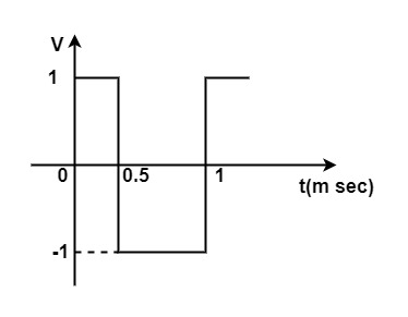
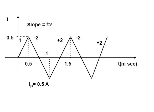
[1987: 2 M] A Square waveform as shown in figure is applied across 1 mH ideal inductor. The current through the inductor is a _______ wave of _________ Peak amplitude.
Explanation:
As we know that , the current through inductor is the integration of the applied voltage across the inductor.
The current through the inductor is a triangular wave.
Triangular wave 0.5 Amp peak.
i_L=\frac1L\int VdtSlope of triangular wave = step change in square wave
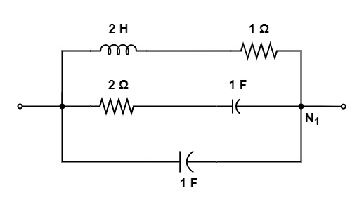
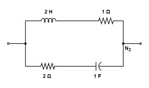
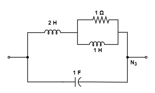
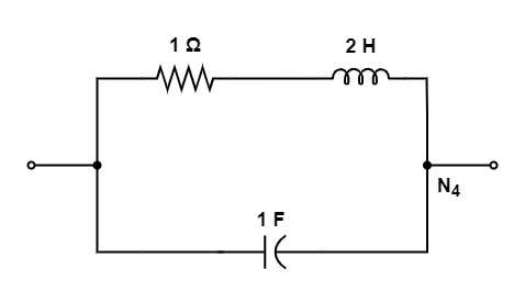
[1992: 2 M] Of the network, N1, N2, N3, and N4 of figure, the network having identical driving point function are
a) N1 and N2
b) N2 and N4
c) N1 and N3
d) N1 and N4
Ans: (c)
Explanation:
Let us consider the network N1, we get
Y1(s) = s+\frac1{2s+1}+\frac1{{\displaystyle\frac1s}+2}
Y1 (s) = \frac{2s^2+2s+1}{2s+1}
Consider the network N2 :
Y2(s)= \frac1{2s+1}+\frac1{2+{\displaystyle\frac1s}}+\frac{1+s}{2s+1}
Let us take the network N3 :
Y3 (s) = s+\frac1{1+{\displaystyle\frac1{1+{\displaystyle\frac1s}}}}
= s+\frac{1+s}{s+1+s}
Y3 (s) = s+\frac{2s^2+2s+1}{2s+1}
Taking network N4 :
Y4 (s) = s+\frac1{2s+1}
\frac{2s^2+s+1}{2s+1}From all these we can see that , N1 and N3 networks having identical driving point function.
So, option (c) is the correct answer.
[1993: 2 M] A network contain linear resistors and ideal voltage sources. If values of all the resistors are doubled, then the voltage across each resistor is
a) halved
b) doubled
c) increased by four time
d) not changed
Ans: (d)
Explanation:
When all resistors are doubled then the current halved.
I = \frac I2
R’ = 2R
V’ = \frac I2.2R
= IR = V
So, option (d) is the correct answer.
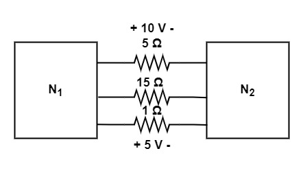
[1993: 2 M]The two electrical subnetwork N1 and N2 are connected through three resistor as shown in fig. The voltages across 5 ohm resistor and 1 ohm resistor are given to be 10 V and 5 V, respectively. Then voltage across 15 resistor is
a) -105 V
b) 105 V
c) -15 V
d) 15 V
Ans: (a)
Explanation: Given that voltage across 5 ohm and 1 ohm resistor is 10 C and 5 V . So,
Current through 5 Ω resistor
i5= \frac{10}5
= 2 Amp.
Current through 1 Ω resistor.
i1 = \frac51
= 5 Amp.
Hence, The current through 15Ω resistor.
i15 =-(i1 + i5)
= -(5 + 2)
= -7 Amp.
Voltage across 15Ω resistor.
V15 =15(i15)
= 15(-7)
= -105 V
So, option (a) is the correct answer.
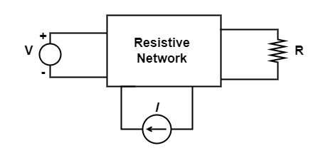
[1995: 1 M] A dc circuit shown in figure has a voltage source V, a current source I and several resistors. A particular resistor R dissipates a power of Watts when V alone is active. The same resistor R dissipates a power of 9 Watts when I alone is Active. The power dissipated by R when both sources are active will be
a) 1 W
b) 5 W
c) 13 W
d) 25 w
Ans: (d)
Explanation:
Given that, P1 = 4W
P2 = 9W
Applying superposition theorem
P = \left(\sqrt{P_1}+\sqrt{P_2}\right)^2
\left(\sqrt4+\sqrt9\right)^2P =(2 + 3)2
= 25 W
So, option (d) is the correct answer.
[1995: 1 M] Two 2 H inductance coils are connected in series and also magnetically coupled to each other the coefficient of coupling being 0.1. The total inductance of the combination can be
a) 0.4 H
b) 3.2 H
c) 4.0 H
d) 4.4 H
Ans: (d)
Explanation: In series combination, the equivalent inductance in series connection can be calculated by ,
L = L1 + L2 ± 2M
= L1 + L2 ± 2k \sqrt{L_1L_2}
L = 2 + 2 ± 2(0.1) \sqrt{2\times2}
= 4 ± 0.4
L = 3.6 H and 4.4 H
∴ The correct option is 4.4 H.
[1997: 1 M] The current i in the circuit of figure is equal to
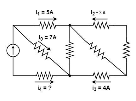
a) 12 A
b) -12 A
c) 4 A
d) None of these
Ans: (b)
Explanation: There are two nodes in the circuit, so now using KCL, we can find the value of I,
Apply KCL at node A
i0 + i1 + i4 = 0
7 + 5 + i4 = 0
i4 = -12 A
∴ The correct option is -12 A.
[1997: 1 M] The voltage V in figure is equal to
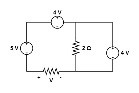
a) 3 V
b) -3 V
c) 5 V
d) None of these
Ans: (a)
Explanation: Given circuit is,
Applying KVL in the circuit we get,
V + 5 – 4 – 4 = 0
V = 3 V
∴ The correct option is 3 V.
[1997: 1 M] The voltage V in figure is always equal to
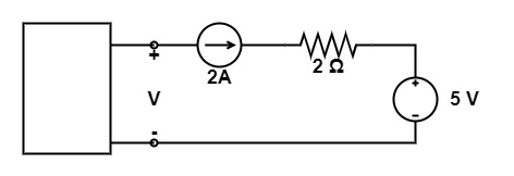
a) 9 v
b) 5 v
c) 1 V
d) None of these
Ans: (d)
Explanation: By solving the circuit, we get that ,
V = V2A + 2 × 2 + 5
V = V2A + 9
The voltage of 2A current source is not known.
Hence, It is not possible to find the value of voltage V.
∴ The Correct option None of these.
[1997: 1 M] The voltage V in figure is
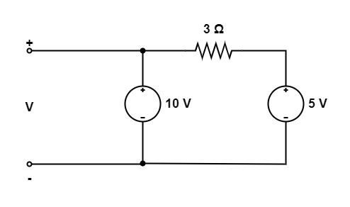
a) 10 V
b) 15 V
c) 5 V
d) None of these
Ans: (a)
Explanation:
We know that, A parallel circuit has two or more paths for current to flow through. Voltage is the same across each component of the parallel circuit. The sum of the currents through each path is equal to the total current that flows from the source.
Voltage in parallel is always equal.
So, option (a) is the correct answer.