Transformers Set-1
[1992: 1 M] Two transformers of the same type, using the same grade of iron and conductor materials, are designed to work at the same flux and current densities; but the linear dimensions of one are two times those of the other in all respects. The ratio kVA of the two transformers closely equals
a) 16
b) 8
c) 4
d) 2
Ans: (a)
Explanation:
Both the developed emf and current carrying capability are the functions of core area. Current carrying capabilities or the current density of the core material is fixed. As the area has increased 4 times, current carrying capability has also increased 4′ times.
The induced emf is directly proportional to core area. Hence it has also increased 4′ times.
Therefore, E2 = 4E1 , I2 = 4I2
So, the KVA is given as,
kVA2 = E2 I2
= 4E1 ✕ 4I1
= 16 E1 I1
The ratio KVA of the two transformers is closely equals to be 16.
[1992: 1 M] A Buchholz relay is used for
a) protection of a transformer against all internal faults.
b) protection of a transformer against external faults.
c) protection of a transformer against both internal and external faults.
d) protection of induction motors.
Ans:(c)
Explanation:
In general, buchholz relay is a safety device which is mounted on oil filled power transformers and reactors, equipped with an external overhead oil reservoir. Buccholz relay is used as a protective device, It is used to detect incipient faults.
It protects transformers against both external and internal faults because Buchholz relay are sensitive to the effects of dielectric failure that can occur inside the equipment they protect.
So, option (c) is the correct answer.
[1993: 2 M] A 50 Hz, 220/400 V, 50 kVA single-phase transformer operates on 220 V, 40 Hz supply with
secondary winding. Then
a) The eddy current loss and hysteresis loss of the transformer decrease.
b) The eddy current loss and hysteresis losssof the transformer increase.
c) The hysteresis loss of the transformer increase while eddy current loss remains the same.
d) The hysteresis loss remains the same whereas eddy current loss decreases.
Ans:(c)
Explanation: It is given that f= 50 Hz, V1= 220 V, V2 = 400 V , KVA = 50 KVA ,
Transformer is operating on V= 220 V , f=40 Hz with secondary winding.
We know that , hystersis loss is given by,
Wh α B1.6m f
wh α \frac{B_m^{1.6}f^{1.6}}{f^{0.6}}\alpha\frac{V^{1.6}}{\left(f\right)^{0.6}} (AS V α Bmf)
We α Bm2 f2 α V2
From this we can say that hysteresis loss of the transformers increases while eddy current loss remains the same.
So, option (c) is the correct answer.
[1994: 1 M] When a transformer winding suffers a short-circuit the adjoining turns of the same winding experience
a) an attractive force
b) a repulsive force
c) no force
d) none of the above
Ans:(c)
Explanation:
Since the direction of current in adjoining turns is same, it will feel force of attraction.
Therefore, no force will act on it. Therefore, option (c) is the correct answer.
[1994: 1 M]Two transformers of identical voltage but of different capacities are operating in parallel. For satisfactory load sharing
a) impedances must be equal
b) per unit impedances must be equal
c) per unit impedances and XR ratios must be equal
d) impedances and X/R ratios must be equal
Ans: (c)
Explanation:
In general, For satisfactory load sharing of two transformer the per unit impedances and X/R ratios must be equal, to operate at same power factor otherwise, transformer with greater leakage reactance operate with lower power factor and the transformer with lower leakage reactance operated with higher power factor.
Option (c) is the correct answer.
[1995: 1 M] The percentage impedance of a 100 kVA, 11 KV/400 V, delta/wye, 50 Hz transformer is 4.5%. For the circulation of half the full load current during reactances are the same. short circuit test, with low voltage terminals shorted, the applied voltage on the high voltage side will be
a) 200 V
b) 247.5 V
c) 250 V
d) 230 V
Ans: (c)
Explanation: It is given that KVA=100, V1=11 kV , V2 = 400 V , f=50 Hz , % impedance = 4.5 %
For half of the rated current, the voltage should behalf of that voltage which will give full load current.
i.e \frac{4.5\times11\times10^3}{100}
= 495 V
For half of the rated current,
V = \frac{495}2
= 247.5 V
The applied voltage on the high voltage side will be 250 V. So, option (c) is the correct answer.
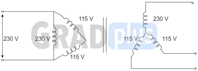
[1995: 1 M] Supply to one terminal of \Delta -Y connected three phase core type transformer which is on no-load fails. Assuming magnetic circuit same, voltages on the secondary side will be
a) 230, 230, 115
b) 230, 115, 115
c) 345, 115, 115
d) 345, 0, 345
Ans: (b)
Explanation : As it is given in that supply to one terminal is \Delta -Y connected , so on the secondary side voltages will be 230, 115,115. Therefore, option (b) is the correct answer.
[1996: 1 M]Keeping in view the requirement of parallel operation, which of the 3-phase connections given below are possible?
a) delta-delta to delta-star
b) delta-delta to star-delta
c) delta-star to delta-star
d) delta-star to star-delta
Ans:(c)
Explanation: Delta-star to delta-star connections are possible in parallel operation.
Transformers in the same phase group can be operated in parallel. The transformer with +30 and -30° angle can be operated in parallel by reversing the primary and secondary phase sequence of one transformer.
So, Option (c) is the correct answer.
[1997: 2 M] The low voltage winding of a 400/230 V, single- phase, 50 Hz transformer is to be connected to a 25 Hz the supply voltage should be
a) 230 V
b) 460 V
c) 115 V
d) 65 V
Ans:(c)
Explanation:
In general, In order to have same value of core flux (V) ratio is to be kept constant. Also in a transformer, core flux is constant.
V α Bm f α \frac{\phi f}A
\frac Vf=K\Rightarrow\frac{V_2}{V_1}=\frac{f_2}{f_1}V2 = \frac{25}{50}\times230
= 115 V
Option (c) is the correct answer.
[1997: 2 M] A voltage V=400 sin314.16tis applied to a single- phase transformer on no-load. If the no-load current of the transformer is 2 sin(314.16t-850).the magnetization branch impedance will be approximately
a) 141 ∠ 900
b) 200 ∠ -850
c) 200 ∠850
d) 282∠-800
Ans: (c)
Explanation: Given that No load voltage is Vo= 400 sin 314.16 t ,
The no -load current is Io = 2 sin (314.6t-85o)
The no-load impedance is given as,
Z0 = \frac V{I_0}=\frac{400}2\angle85^\circ
= 200 ∠ 850 Ω
The magnetization branch impedance will be 200\angle85^o
So, option (c) is the correct answer.