
From generating stations to the consumers, the voltage is stepped up or stepped down several times for economic reasons and every time a three – phase transformer is required.
Magnetising Inrush
Whenever a fresh transformer is initially energized on No-Load, it experiences a sudden surge of current known as magnetizing inrush.
The difficulties produced due to the occurrence of magnetizing inrush are the inappropriate operation of the machines, failure of relay systems, unbalanced voltage in the transformer windings, increase in voltage drop in the power system during energization of power transformer Let us understand this Inrush phenomenon in detail
What is Magnetising Inrush current
Whenever a fresh transformer is initially energized on No-Load, there is a sudden inrush of primary current in it. The maximum value achieved by flux is over twice the normal flux. The core is driven far into saturation, which results in high peak value of magnetizing current.
This phenomenon is known as magnetizing inrush current.
Let us understand this with the diagrams.
See figure 1 in which a fresh un-loaded transformer is switch on.
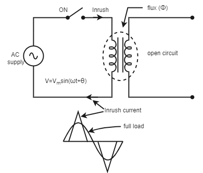
Fig.1 :- Inrush Phenomenon in unloaded transformer
From figure 1, we can see the inrush current is flowing in primary side of an unloaded transformer. The waveform below shows the comparison of inrush current and full load current when the transformer is under operation.
Let the flux in transformer is
φ = φm sin ωt
Induced voltage ,
V= N\frac{d\phi }{dt}= N\frac{d}{dt}(\phi _{m}sin \omega t)= N \phi _{m} \; \omega\; cos t
= N \phi _{m} \; \omega\; sin (\omega t+90^{o})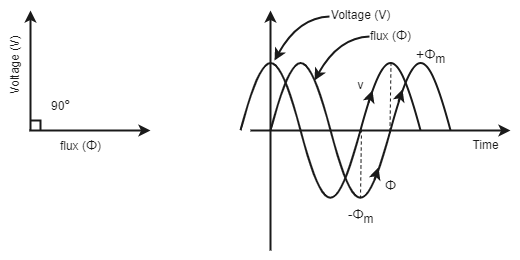
Fig. (2) :- Flux lags applied voltage by 90o.
From fig. (2) we see that, the flux lags the supply voltage by 90˚ during steady state condition, as the supply voltage is equivalent to the voltage induced.
i) When voltage passes through zero and becomes positive, flux should be at its negative maxima and increasing.
ii) During negative half cycle, flux changes from -Φm to Φm .
Therefore, the change in flux is 2Φm in T/2 seconds. This is the scenario in the steady state.
Figure 3 demonstrates the inrush phenomenon in power transformer. It can be seen that whenever applied voltage crosses zero to positive half, then the flux must move to negative maxima. During the first half cycle, flux changes from to -Φm to Φm . Thus, change of flux is 2Φm during normal operation of power transformer.
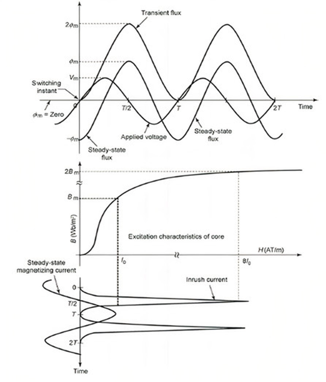
Fig.3 :- Inrush Phenomenon in Power transformer
i) Assuming that transformer is switched on at positive zero crossing of voltage waveform and residual flux is zero.
ii) Therefore, flux will reach a peak value of +2Φm in a half cycle ( known as doubling effect) and the core goes into deep saturation.
iii) The magnetizing current required for producing such a large flux in the core is around 10 times the normal magnetizing current.
iv) This large magnetizing current has peaky non-sinusoidal waveform and it is known as inrush current. This is a transient condition and its time constant could be of the order of few seconds at worst.
The mathematical equations for Inrush current.
Supply voltage v = Vm sin ( \omega t + \theta )
\theta is the switching instant of transformer.
Assuming \Phi as the instantaneous flux.
N\frac{d\phi }{dt} = v N\frac{d\phi }{dt} = V_{m} sin (\omega t +\theta ) \frac{d\phi }{dt} = \left ( \frac{V_{m}}{N} \right )sin (\omega t +\theta ) dt \phi = - \left ( \frac{V_{m}}{N} \right )\int sin (\omega t + \theta )dt\phi = - \left ( \frac{V_{m}}{N\omega } \right ) cos (\omega t + \theta )+K —(1)
K is the integration constant and its value can be found out when t = 0, \phi= \phi_{R} = residual flux. Replacing this initial condition in equation (1) ,
\phi_{R} = - \left ( \frac{V_{m}}{N\omega } \right ) cos (\omega t + \theta )+Kwhich gives K as
K = \phi_{R} + \left ( \frac{V_{m}}{N\omega } \right ) cos (\theta)
Therefore, immediately after the switching, the flux in the transformer will be
\phi = \phi_{R} + \left ( \frac{V_{m}}{N\omega } \right ) cos (\theta ) - \left ( \frac{V_{m}}{N\omega } \right ) cos (\omega t +\theta )Taking \left ( \frac{V_{m}}{N\omega } \right ) as \phi_{m} gives the maximum flux as,
\phi =\phi {R}+\phi {m}cos (\theta )-\phi _{m}cos (\omega t + \theta )v) The flux in the transformer depends on :
1. Residual flux , \phi {R}
2. Switching Instant \theta
3. Magnetic properties of the core.
Further, at \omega t=\pi radians, \theta =0 and \phi {R}= + \phi {m} the flux approaches the maximum of 3 \phi {m} .
So, the primary side of the transformer fetches a huge inrush current having a non – sinusoidal and peaky waveform.
Another type of inrush condition is seen when unexpected variations in the system voltage occur. This sudden variation may be the rapid regaining of system voltage during external fault clearing time. This type of inrush is known as Recovery Inrush.
One more type of inrush is known as sympathetic inrush. This transient can occur in parallel-connected transformers in which one or more transformer is already in operation. When an unenergized transformer is switched into service, the transformer(s) that are already in operation will go into saturation.
Hope, so, this article has made the concept of inrush current clear to you.
Do not forget to check our Awesome GATE courses.