Aspiring engineers who are preparing for the Graduate Aptitude Test in Engineering (GATE) understand the significance of thorough preparation and comprehensive study resources.
Through a meticulous examination of previous years’ question papers, we aim to provide you with valuable insights, key trends, and effective strategies to excel in Power Electronics for your GATE exam.
GATE EE Syllabus for the Subject Power Electronics
Static V-I characteristics and firing/gating circuits for Thyristor, MOSFET, IGBT;
DC to DC conversion: Buck, Boost and Buck-Boost Converters; Single and three-phase configuration of uncontrolled rectifiers; Voltage and Current commutated Thyristor
Based converters; Bidirectional ac to dc voltage source converters; Magnitude and Phase of line current harmonics for uncontrolled and thyristor based converters;
Power factor and Distortion Factor of ac to dc converters; Single-phase and three-phase voltage and current source inverters, sinusoidal pulse width modulation
Analysis of Previous GATE Papers for Power Electronics
| Year | Percentage of Marks |
|---|---|
| 2023 | 6% |
| 2022 | 11 % |
| 2021 | 9 % |
| 2020 | 8 % |
| 2019 | 10 % |
| 2018 | 10 % |
| 2017 | 8% |
| 2016 | 8% |
| 2015 | 11 % |
| 2014 | 6 % |
| 2013 | 8 % |
Recent GATE Paper Questions of Power Electronics
The following questions have been asked from Power Electronics , in GATE-EE 2023 Paper.
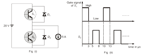
Q. The chopper circuit shown in figure (i) feeds power to a 5 A DC constant current source. The switching frequency of the chopper is 100 kHz. All the components can be assumed to ideal, The gate signals of switches S1 and S2 and See are shown in figure (ii) Average voltage across the 5 A current source is

(a) 10 v
b) 6 V
(c) 12 V
d) 20 V
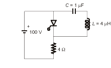
Q. The circuit shown in the figure has reached steady state with thyristor Tin OFF condition. Assume that the latching and holding currents of the thyristor are zero. The thyristor is turned ON at t = 0 sec. The duration in microseconds for which the thyristor would conduct, before it turns off, is _____. (Round off to 2 decimal places).

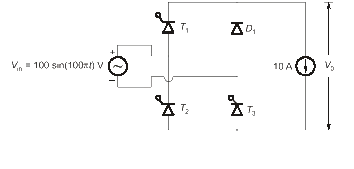
Q. The single phase rectifier consisting of three thyristors T1, T2, T3 and a diode Dl feed power to a 10 A constant current load. Tl and T3 are fired at \alpha=60^{o} and T2 is is fired at \alpha=120^{o}, The reference for a is the positive zero crossing of V . The average voltage Vo across the load in volts is (Round Off to 2 decimal places).

GATE Paper Solutions for Power Electronics
Last 25+ years GATE Papers with Authentic Solutions
Best Course for Power Electronics
By Mr. Ratiranjan Behra


