Block Diagrams and SFG Set-1
[1991: 2M] The signal flow graph of figure shown below, has _______forward paths and ______feedback loops.
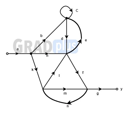
Explanation: From the given signal flow graph, we get
Number of forward paths = 4 (abdfg, ahfg, aklfg, akmg)
Number of loops = 4 (c, de, Ifn, mn)
Therefore , it has 4 forward path and 4 number of loops.
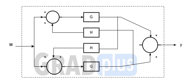
[1992: 1 M] The overall transfer function of the system shown in figure is
a) \frac G{1-GH}
b) \frac{2G}{1-GH}
c) \frac{GH}{1-GH}
d) \frac{GH}{1-H}
Ans: (b)
Explanation: AS the given block diagram is,
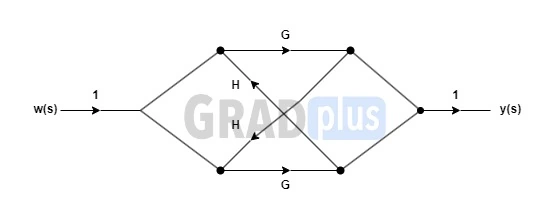
So, from the SFG can be drawn as,
The transfer function is given by,
∴ T.F.=\frac{G+GHG+G+GHG}{1-\lbrack GHGH\rbrack} ….. (4 Forward paths are there)
= \frac{2G}{1-GH}
Therefore, option (b) is the correct answer.
[1993: 1 M] Signal flow graph is used to obtain the
a) Stability of a system
b) transfer function of a system
c) controllability of a system
d) observability of a system
Ans: (b)
Explanation:
Signal flow graph is used to find the transfer function between the out put and input node.
Signal flow graph is a graphical representation of a system that shows the flow of signals through the system.
It is a useful tool for analyzing and designing systems in various fields such as electrical engineering, control systems, and communication systems.
So, option (b) is the correct answer.
[1995: 1 M] The closed loop transfer function of a control system is given by
\frac{C\left(s\right)}{R\left(s\right)}=\frac{2\left(s-1\right)}{\left(s+2\right)\left(s+1\right)}For a unit step input the output is
a) -3e-2t + 4e-t – 1
b) -3e-2t -4e-t + 1
c) zero
d) infinity
Ans: (a)
Explanation: It is given that,
\frac{C\left(s\right)}{1/s}=\frac{2\left(s-1\right)}{\left(s+2\right)\left(s+1\right)} C\left(s\right)=\frac{-1}s+\frac{-3}{s+2}+\frac4{s+1}∴ C(t)= -1-3e-2t +4e-t
For the unit step input, the output is , -1-3e-2t +4e-t.
Option (a) is the correct answer.
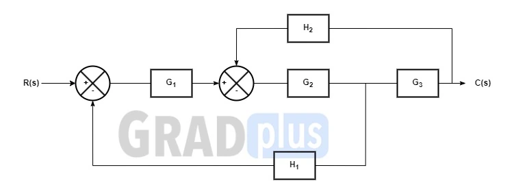
[1998: 2 M]For block diagram shown in figure C(s)/R(s) is given by
a) \frac{G_1G_2G_3}{1+H_2G_2G_3+H_1G_1G_2}
b) \frac{G_1G_2G_3}{1+G_1G_2G_3+H_1H_2}
c) \frac{G_1G_2G_3}{1+G_1G_2G_3H_1+G_1G_2G_3H_1H_2}
d) \frac{G_1G_2G_3}{1+G_1G_2G_3H_1}
Ans: (a)
Explanation: Give block diagram is,
From the diagrams,
Number of forward paths
= 1(G1G2G3)
Number of loops
= 2 (-G1G2H1, – G2G3H2)
Number of non-touching loops = 0
T.F. = =\frac{C\left(s\right)}{R\left(s\right)}=\frac{G_1G_2G_3}{1+H_1G_1G_2+H_2G_2G_3}
Therefore, option (a) is the correct answer.
[2000: 1 M] A linear time invariant system initially at rest, when subjected to a unit step input, gives a response y(t)=te-t, t > 0. The transfer function of the system is
a) \frac1{\left(s+1\right)^2}
b) \frac1{s\left(s+1\right)^2}
c) \frac1{\left(s+1\right)^2}
d) \frac1{s\left(s+1\right)}
Ans: (c)
Explanation:
X(s) = Lu(t)= \frac1s
Y(s) = L te-t = \frac1{\left(s+1\right)^2}
∴ T.F. = \frac{Y\left(s\right)}{X\left(s\right)}=\frac s{\left(s+1\right)^2}
Option (c) is the correct answer.
[2002: 2 M] The transfer function of the system described by \frac{d^2Y}{dt^2}+\frac{dy}{dt}=\frac{du}{dt}+2u with u as input and y as output is
a) \frac{\left(s+2\right)}{\left(s^2+s\right)}
b) \frac{\left(s+1\right)}{\left(s^2+s\right)}
c) \frac2{\left(s^2+s\right)}
d) \frac2{\left(s^2+s\right)}
Ans: (c)
Expalanation: Given that,
\frac{d^2Y}{dt^2}+\frac{dy}{dt}=\frac{du}{dt}+2u⇒ s2Y(s) + sY(s) = sU(s) + 2U(s)
\therefore\frac{Y\left(s\right)}{U\left(s\right)}=\frac{s+2}{\left(s^2+s\right)}Option (c) is the correct answer.
[2003: 1 M] A control system is defined by the following mathematical relationship
\frac{d^2x}{dt^2}+6\frac{dx}{dt}+5x=12\left(1-e^{-2t}\right)The response of the system as t \Rightarrow \infty is
a) x = 6
b) x = 2
c) x = 2.4
d) x = -2
Ans: (c)
Explanation: It is given that ,
\frac{d^2x}{dt^2}+6\frac{dx}{dt}+5x=12\left(1-e^{-2t}\right)Taking (LT) on the sides
(s + 6s+5)X(s)= 12 \left(\frac1s-\frac1{s+2}\right)
= \frac{24}{s\left(s+2\right)}
X(s)= \frac{24}{s\left(s+2\right)\left(s+1\right)\left(s+5\right)}
Response at t \Rightarrow \infty
Using final value theorem
\underset{t\rightarrow\infty}{Lt}x(t)=\underset{s\rightarrow0}{Lt}sX\left(s\right)= \underset{s\rightarrow0}{Lt}\frac{s\times24}{s\left(s+1\right)\left(s+2\right)\left(s+5\right)}
Option (c) is the correct answer.
[2003: 2 M] A control system with certain excitation is governed by tthe following mathematical equation \frac{d^{2}x}{dt^{2}}+\frac{1}{2}\frac{dx}{dt}+\frac{1}{18}x=10+5e^{-4t}+2e^{-5t} The natural time constant of the response of system are
a) 2s and 5s
b) 3s and 6s
c) 4s and 5s
d) 1/3s and 1/6s
Ans: (b)
Explanation: Given equation is, \frac{d^{2}x}{dt^{2}}+\frac{1}{2}\frac{dx}{dt}+\frac{1}{18}x=10+5e^{-4t}+2e^{-5t}. The given differential equation is a second order linear homogenous equation .
We know that, Natural time constant of the response depends only on poles of the system.
T(s)= \frac1{s^2+s/2+1/18}
\frac{18}{18s^2+9s+1} \frac{18}{\left(6s+1\right)\left(3s+1\right)}This is in the form\frac1{\left(1+sT_1\right)\left(1+sT_2\right)}
∴ T1, T2 = 6 sec, 3 sec.
Option (b) is the correct answer.
[2003: 2 M] The block diagram of a control system is Shown in figure. The transfer function G(s) = Y(s)/U(s) of the system is
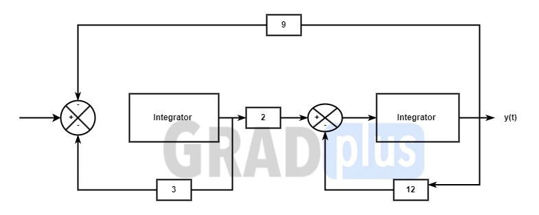
a) \frac1{18\left(1+{\displaystyle\frac s{12}}\right)\left(1+{\displaystyle\frac s3}\right)}
b) \frac1{27\left(1+{\displaystyle\frac s6}\right)\left(1+{\displaystyle\frac s9}\right)}
c) \frac1{27\left(1+{\displaystyle\frac s{12}}\right)\left(1+{\displaystyle\frac s9}\right)}
d) \frac1{27\left(1+{\displaystyle\frac s9}\right)\left(1+{\displaystyle\frac s3}\right)}
Ans: (b)
Explanation:
As it is said that the Integrator are represemnted as 1/s in s-domain , so the diagram becomes,
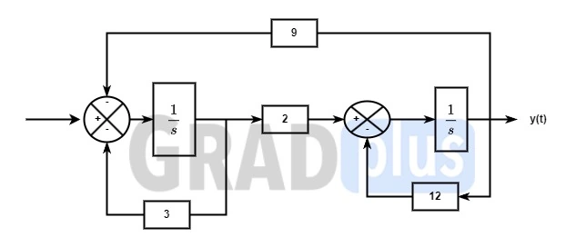
As per the block diagram, the corresponding signal flow graph is drawn
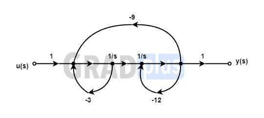
One forward path P1 = 2/s2
The individual loops are,
L_1=-\frac3s,\;L_2=-\frac{12}sand\;L_3=-\frac{18}{s^2}From the signal flow graph, we can see that , there is one forward path, and two non-touching loops.
L1 and L2 are non-touching loops
L1L2= \frac{36}{s^2}
The loops touches the forward Path ∆1 = 1
The graph determinant is
∆ 1 -(L1 + L2 + L3)+ L1L2
= =1+\frac3s+\frac{12}s+\frac{18}{s^2}+\frac{36}{s^2}
Applying Mason,s gain formula ,
G(s)= \frac{Y(s)}{U(s)}=\frac{P_1\triangle_1}\triangle
= \frac2{s^2+15s+54} \frac2{\left(s+9\right)\left(s+6\right)} \frac1{27\left(1+{\displaystyle\frac s9}\right)\left(1+{\displaystyle\frac s6}\right)}Therefore, option (b) is the correct answer.