
In Electrical Machines, transformer is a cornerstone. It serves as an vital link in the transmission and distribution of electrical energy. We all know that transformer is a device which transfers electrical energy from one circuit to another by keeping its frequency constant.
Understanding the equivalent circuit helps engineers design transformers for specific applications, optimize their performance, and predict how they will behave under different load conditions. It’s a fundamental concept for anyone studying electrical engineering or working with Electrical Machines.
In this article, we are going to delve the detailed information about the equivalent circuit of the transformer.
You can watch a quick YouTube video or read along.
What is Equivalent Circuit of transformer?
● Equivalent Circuit of transformer is a compact and efficient means of describing or predicting that how well the transformer will work.
● The knowledge about equivalent circuit is very important in estimating and checking the performance of transformer under all load conditions i.e. from no load to full load including short-circuited secondary.
● It makes calculations and analysis easier because we are working in one winding only, which is more convenient.
● The accurate efficiency and voltage regulation calculations can be easily done and can be compared with requirements. It ensures that there have been no errors in design and construction of transformers.
● Its important to know the value of percentage impedance during installing a transformer in existing power system because the value of %Z of all the transformers should be matched properly during the parallel operation of power transformer.
Let us see the equivalent circuits of transformer one by one.
i) Basic Magnetically coupled circuit
The equivalent circuit of basic magnetically coupled circuit is shown below.

Primary and secondary parameters are listed below.
Io → no load current , \overline{I_{c}}+\overline{I_{m}}
Ic → core loss current , Im → magnetising current
Rc → core loss resistance , Xm → magnetising reactance
I1 → primary current , I2 → Secondary current
V1 → Primary voltage , V2 → Secondary voltage
R1 → Primary resistance , R2 → Secondary resistance
XL1 → Primary leakage reactance , XL2 → Secondary leakage reactance
E1 and E2 → Primary and secondary induced EMf
N1 and N2 → No. of turns of primary and secondary
The impedance is the sum of resistance and reactance. Therefore, primary and secondary impedances will become,
Z1 = R1+ jXL1 , Z2 = R2 + jXL2
Exact equivalent circuit is difficult to analyze due to no-load branch of Rc and Xm. Therefore, we shift this branch to supply side without losing much accuracy.
Now, to make calculations simpler, we will shift all the circuit parameters from one side to other.
The equivalent circuit will now become

In this we have transferred the secondary parameters to primary side for making calculations simple.
When we shift the parameters like R2 and X2 to primary side it will change into
R2 → R2‘
X2 → X2‘
Cu loss by R2 in sec. = Cu loss produced carrying current I1 in pri
I22R2 = I12 R2‘
R_{2}^{'}=\left ( \frac{I_{2}}{I_{1}} \right )^{2}R_{2}R_{2}^{'}= \frac{R_{2}}{K^{2}} [ Secondary resistance referred to primary)
Similarly when we transfer reactance to primary side it will be XL2‘ to the primary side
X_{L2}^{'}= \frac{X_{L2}}{K^{2}}The equivalent resistance referred to primary is given as,
Ro1 = R1 + R2‘
= R_{1}+\frac{R_{2}}{K^{2}}
Equivalent leakage reactance referred to primary
Xo1 = XL1 + XL2‘
= X_{L1}+\frac{X_{L2}}{K^{2}}
Total Impedance referred to primary side
\overline{Z_{o1}}=R_{o1}+jX_{o1}|\overline{Z_{o1}}|=\sqrt{R^{2}{o1}+X^{2}{o1}}
The total resistance referred to primary side
Ro1 = R_{1}+\frac{R_{2}}{K^{2}}
The total leakage reactance referred to primary is given as,
Xo1 = X_{L1}+\frac{X_{L2}}{K^{2}}
Total impedance Primary Side
\overline{Z_{o1}}=R_{o1}+jX_{o1}Approximate Equivalent Circuit Referred to primary is
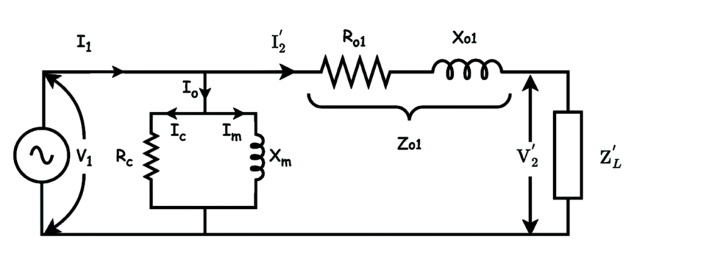
c) Exact Equivalent Circuit Referred to secondary side

Transferring R1 to the secondary side
Cu loss by R1 in pri. = Cu loss produced carrying current I2 in sec
I12R1 = I22R1‘
R_{1}^{'}=\left ( \frac{I_{1}}{I_{2}} \right )^{2}R_{1}R1‘ = K2R1
Primary resistance referred to secondary side
Similarly transferring XL1 to the secondary side
XL1‘ = K2 XL1
This is the primary leakage reactance referred to secondary side.
Equivalent Resistance referred to secondary
Ro2 = R2 + R1‘ = R2 +K2R1
Equivalent leakage reactance referred to secondary
Xo2 = XL2 + XL1‘
Xo2 = XL2 +K2XL1
Total impedance secondary side is
\overline{Z_{o2}}=R_{o2}+jX_{o2}|\overline{Z_{o2}}|=\sqrt{R^{2}{o2}+X^{2}{o2}}
Copper losses is given by
Pcu = Pcu1 + Pcu2
Pcu = I12R1 + I22R2
= I12R1 + I12R2‘
= I12(R1+R2‘)
Pcu = I12 Ro1 —(a)
Pcu = I22R2 + I22R1‘ = I22(R2+R1‘)
Pcu = I22 Ro2 —(b)
Equating eq.(i) and (ii) we get,
\frac{R_{o1}}{R_{o2}}=\left ( \frac{I_{2}}{I_{1}} \right )^{2} \frac{R_{o1}}{R_{o2}}=\left ( \frac{I_{2}}{I_{1}} \right )^{2}=\frac{1}{K^{2}} R_{o1}=\frac{R_{o2}}{K^{2}}Ro2 = K2 Ro1
Other Equivalent Parameters
i) Secondary parameter referred to primary
V_{2}^{'}= \frac{V_{2}}{K} E_{2}^{'}= \frac{E_{2}}{K}I2‘ = KI2
K= \frac{N_2}{N_1} R_{L}^{'}=\frac{R_{L}}{K^{2}} X_{L}^{'}=\frac{X_{L}}{K^{2}} Z_{L}^{'}=\frac{Z_{L}}{K^{2}} Z_{L}^{'}=\sqrt{R_{L}^{'2}+X_{L}^{'2}}2) primary parameter referred to Secondary
V1‘ = KV1
E1‘ = KE1
I_{c^{'}}=\frac{I_{c}}{K} I_{m^{'}}=\frac{I_{m}}{K} I_{o^{'}}=\frac{I_{o}}{K}and I_{1^{'}}=\frac{I_{1}}{K}
Rc‘ = K2Rc
Xm‘ = K2Xm
The approximate Equivalent Circuit Referred to secondary is
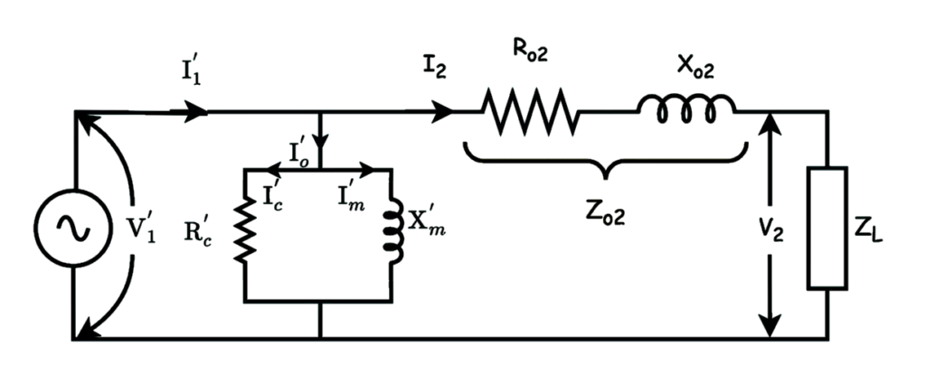
In this way, we can draw the equivalent circuits for the primary and secondary side.
Using the equivalent circuit, engineers can perform calculations and simulations to understand how a transformer responds to changes in load, voltage, and other parameters.
This allows for efficient design, optimization, and troubleshooting of transformer-based systems.
Hope, so this article helped you to understand the equivalent circuit of transformers thoroughly.